Modeling in the Schematic Viewport
You can build Fusion models using Modo's Schematic Viewport instead of using the 3D viewport. The Schematic Fusion layout supports the full range of Boolean expressions, and allows the use of mesh instances and sharing of meshes between multiple Fusion Items.
Schematic Fusion has been designed to be user-friendly with quick access to common features. There are a number of common shortcuts in the Schematic Pie Menu and context menus.
Note: Schematic Fusion modeling is not compatible with the new MeshFusion workflow introduced in Modo 10.2. You can still edit your model in the Schematic, but you then need to convert it to the new format. For more details on how to do this, see Legacy Fusion Items.
Note: Drag-and-drop uses the new workflow commands, so it's not compatible with legacy Schematic Fusion editing.
Creating a Schematic Fusion
In order to use Schematic Fusion, you must first create a Fusion Item using the New Fusion button. See Creating a New Fusion Item on how to do this.
A Schematic Fusion Item is created automatically. You can see it when you switch to the Schematic Fusion layout.
Schematic Fusion Layout
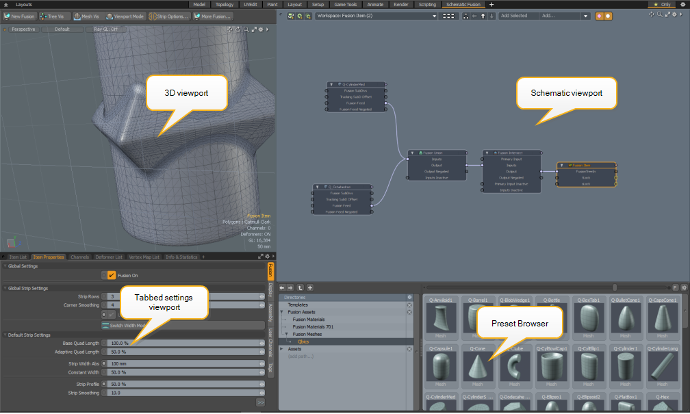
The default Schematic Fusion layout is divided into four viewports. The image below shows how the layout is organized. Click the image to enlarge it.
Schematic Pie Menu
The Schematic pie menu provides a shortcut to the most common Fusion commands. Position the mouse over the Schematic viewport and press Ctrl+F to open the Schematic pie menu.

The menu offers the following options (clockwise from the top):
• Clear Extra Mesh Channels - Remove any channels not related to Fusion.
• Add Fusion Union Node - Add a union node to the Schematic.
• Add Fusion Intersect Node - Add an intersect node to the Schematic.
• Add Fusion Subtract Node - Add a subtract node to the Schematic.
• More Schematic Fusion... - Open additional Schematic options.
• Delete Unused Fusion Nodes - Remove all childless nodes.
• Prep & Add Selected Meshes - Prepare all selected items for use in Schematic Fusion, and add them to the Schematic workspace, ready to be used in the Fusion mesh.
• Instance & Add Selected Meshes - Create an instance of each selected item and the instance(s) to the Schematic workspace, ready to be used in the Fusion mesh.
Note: Any changes to the original mesh are applied to the instance.
Prepping Items
To add a mesh to the Schematic, you must first prepare it so that its node has the necessary inputs and outputs. If you don't prep it, the mesh node doesn't have a Fusion Feed output and cannot be connected to a Boolean operator.
Let's say you want to add a Qbic primitive to the Schematic:
| 1. | In the Schematic Fusion layout, double-click a Qbic preset in the Preset Browser (lower-right) to add it to the scene. |
| 2. | With the item selected and the cursor over the Schematic viewport, press Ctrl+F to open the pie menu, and select Prep & Add Selected Meshes. |
The node appears in the Schematic viewport.
Note: If the mesh is already in the Item List, skip step 1.
You can also prep the mesh by clicking More Fusion... above the 3D viewport and selecting Prep Selected. You can then add the mesh to the Schematic by dragging it from the Item List or the 3D viewport.
Pruning the Schematic Fusion
There may be times when you are left with nodes that have no children, which do not affect the Fusion mesh.
If you want to remove the nodes and tidy the Schematic, follow these steps:
| 1. | With the mouse over the Schematic workspace, press Ctrl+F to open the pie menu. |
| 2. | Select Delete Unused Fusion Nodes. |
Schematic Fusion Item
When you create a Fusion model, a Fusion Item node is added to the Schematic viewport. This is required to produce a Fusion model. The results of each branch are fed into the FusionTreeIn input.
A Fusion item has an extensive set of properties that are detailed in Fusion Item.
Fusion Nodes
There are three types of node in any Fusion graph:
• Meshes - The source geometry. Only the Fusion channel outputs are used and they can be connected to Fusion operation nodes.
• Fusion Operations - Fusion Union, Fusion Intersection, and Fusion Subtract. These take input from Fusion output channels of meshes and/or other Fusion operation nodes. Their output channels may connect to other operation nodes or to the Fusion item.
• Fusion Item - Accepts a single output from a Fusion operation node only.
You typically take the Fusion Feed output from a mesh and wire it into the appropriate input of the Boolean operator. Remember to prep the mesh in order to have the Fusion Feed output. The various branches of the node graph are fed into a Fusion Intersect node to combine the branches. The flow then terminates in the Fusion Item.
Meshes
Meshes must be prepped as Fusion Source meshes. This process adds their two Fusion channels:
• Fusion Feed - Adds positive version of mesh to Fusion.
• Fusion Feed Negated - Adds negative version of mesh to Fusion. See Fusion Feed Negated for more information.
Operation Nodes
Operation nodes determine the Boolean operation performed using their inputs. You can add an operation node to the Schematic by clicking Add... at the top of the Schematic workspace. They are found under Channel Modifiers > Other.
Note: To quickly locate a Boolean operation node, type part of the name into the search field after clicking Add....
Fusion Union
Fusion Union makes use of the following channels:
• Input - Any combination of meshes and outputs of other operation nodes.
• Output - The Boolean union of all inputs.
• Inputs Inactive - The inputs are swapped here when you select Fusion Node Options > Deactivate All from the context menu. You can reinstate them by selecting Activate All.
Note: To open the context menu, right-click on the node title.
Fusion Intersect
Fusion Intersect makes use of the following channels:
• Primary Input - The primary input is used to set the initial geometry for the intersection. This is required because intersections are performed sequentially, and the order of those operations can affect the result. The input is either a mesh or the output of another operation node. All other inputs (attached to the Inputs channel) are applied to this initial geometry.
Note: Having something connected to the Primary Input channel is not required, unless you need to control the order of operation. If it is not used, intersections are simply carried out in the order they were connected to the Inputs channel.
• Inputs - Any number of meshes and/or outputs of other operation nodes.
• Output - The Boolean result of the inputs.
• Output Negated - The negated Boolean result of the inputs.
• Primary Input Inactive - The Primary Input is swapped here when you select Fusion Node Options > Deactivate All from the context menu. You can reinstate it by selecting Activate All.
• Inputs Inactive - The inputs are swapped here when you select Fusion Node Options > Deactivate All from the context menu. You can reinstate them by selecting Activate All.
For Primary Input, the best practice is to think of it as the initial volume, and all additional inputs as geometry that trims away from that volume (all intersections remove volume). This is important because of Fusion’s support of open surfaces. (Traditional Booleans are restricted to closed volumes, in which the order of intersection doesn't matter.)
For example, say you have a sphere as the Primary, and several one-sided planes as inputs, slicing away parts of the sphere. If you tried to first intersect the planes, it might fail. Intersecting two finite planes does not describe a surface or volume, and subsequent intersections would have nothing to interact with. Connecting the sphere to the Primary Input solves this.
Note: Be careful with open surfaces as their edges must be outside of the Boolean volume.
Fusion Subtract
The Fusion subtract node uses the following channels:
• Input A - The initial geometry to subtract from. This must be a single item (although it can be the output of another operation, which may itself have many inputs).
• Input B - The geometry to subtract from Input A. This must be a single item (although it can be the output of another operation, which may itself have many inputs).
• Output - The Boolean result of the subtraction.
• Output Negated -The negated Boolean result of the subtraction.
Note: We recommend against the use of subtraction nodes. Although they may seem more straightforward, they are less flexible and less efficient than using intersection. A negated intersection is the same as a subtraction. See Fusion Feed Negated.
Fusion Item Node
The Fusion Item node uses the following channel:
• FusionTreeIn - Accepts a single output from operation nodes only. This takes the output from the last operation node in the graph.
Fusion Feed Negated
Negating the feed generates a mesh with reversed geometry, similar to flipping the polygons. This is useful for when you want to have multiple subtractive elements on a mesh, which is difficult to achieve with Boolean subtraction.
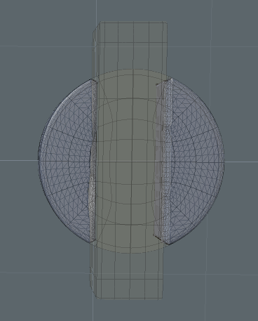
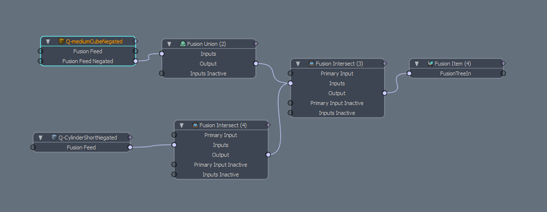
A negated intersection is equivalent to a subtraction (intersections always remove geometry). With a normal intersection, all geometry is subtracted except for the geometry that is within both meshes. However, an intersection using Fusion Feed Negated subtracts the negated mesh and leaves the rest of the other mesh that is outside the negated mesh. The images below show the difference, the corresponding schematic is shown to the right of the result.

|

|
|
Above: Intersection with normal rectangle. |
|
|
|
|
Above: Intersection with negated rectangle. |
|
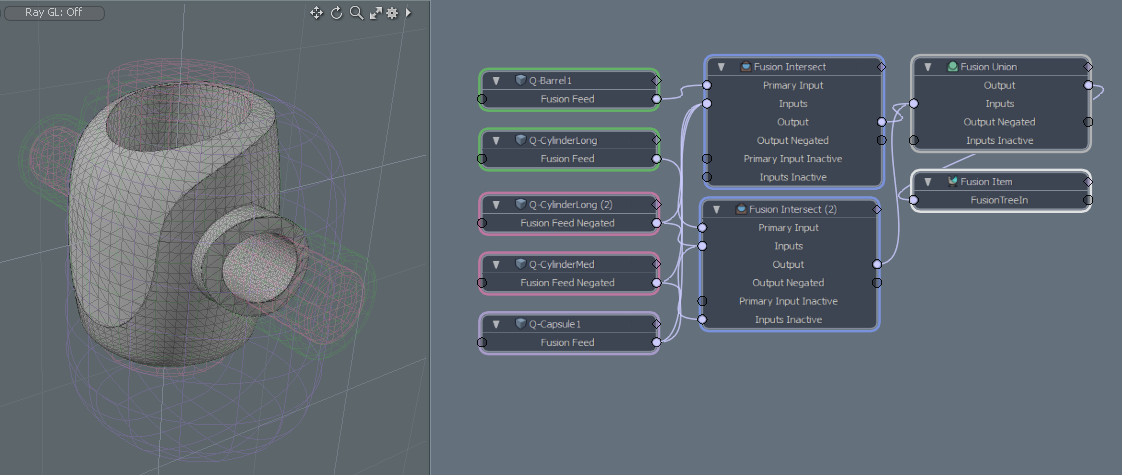
The image below shows a simple mesh that is constructed by intersecting negated cylinders (one original and two instances) with a single mesh.

Note: You can also use subtraction to achieve the effect demonstrated above, by unifying the three small cylinders before subtracting the result from the larger cylinder.