Schematic Viewport
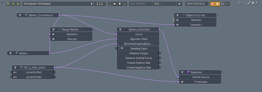
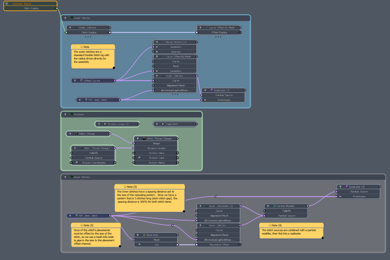
The 3D viewports give you a means to visually edit your scenes in a fully 3D environment. While great for laying out models, it's not as effective at setting up symbolic relationships between items and their channels. This particular activity is better suited to the Schematic viewport, a 2D environment where elements are visually linked, providing a more intuitive and powerful way to define relationships between elements; building networks of operations that combine to produce a specific result. This is, in a way, is like a graphic programming paradigm, where you define a flow of information through the network of elements visually.
In the Schematic viewport, you work with nodes, which are simple 2D representations of items that exist only within the Schematic. Each node signifies an item, an operation, or a function and its associated channels. The combinations of these nodes and their symbolic links create networks known as graphs. You use nodal graphs commonly in rigging (creating simple controls for complex actions). Modo extends this workflow by using the same functionality for dynamics, particles, and shading as well. Mainly, you use the Schematic viewport with the Channels Viewport and link channels together with a drag-and-drop process.
Navigating in the Viewport
The default Schematic view is similar to the UV view, where you view and work with flat, two-dimensional representations of information. You can navigate the view of complex node graphs using the navigation icons in the upper-right corner of the viewport. For example, drag the arrow icon to pan the view, or click the magnifying glass icon to zoom into the view. You can also use keyboard shortcuts to navigate: Alt+click and drag to pan and Ctrl+Alt+click and drag to zoom. Alternately, with a scroll wheel and multi-button mouse, you can middle-click and drag to pan and roll the scroll wheel to zoom.
Tip: The Schematic view, as other viewports, can be split to show multiple views, or even cloned to show a workspace in one view and the contents of an assembly in another view for simultaneous editing.
Adding and Arranging Nodes
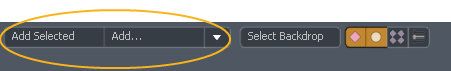
When first opening the Schematic view (in the Setup layout), you see an empty workspace. Modo needs to first know what elements you want to work with. To add the elements, you can drag any item from the 3D (OpenGL) Viewport, the Items (Scenes) List, any attribute in the Properties panel, or the Channels Viewport directly into the Schematic view. You can add multiple items by pressing the Shift key as you select multiple elements before dragging them. You can also click the Add Selected button at the top of the viewport to automatically add any selected items or channels. You can add additional components, such as modifiers or constraints, using the Add menu at the top of the viewport, which lists all the available item types. Click an item to add it to the current Schematic workspace and the Items list.
When adding channels, you can drag them anywhere in the viewport and they are automatically added to their respective items. Doing this adds the associated item node as well if it wasn't already there. On a drag-and-drop operation, if you pause before dropping the item or channels into the viewport, a drop action menu appears with a number of contextually appropriate options for the drop operation.
Once you add an element, Modo displays it as a gray rectangular box, referred to as a node. The node is a bar with an icon and title (the same name as its representation in the Items list). As you add related channels, the box expands to accommodate them.
To duplicate a node, right-click it and click Node Duplicate > Duplicate. You can also select it, then press Ctrl+D on the keyboard. To create an instance of the node, right-click it and click Node Duplicate > Instance. You can also select it, then press Shift+D on the keyboard.
You may find it easier to work with the nodes by organizing them and arranging them in the view. To do this, click the node header (the name or title bar) and drag it to a new position. Modo snaps the nodes into positions in relation to surrounding nodes to place and align nodes for an orderly Schematic.
Tip: You can customize the node snapping behavior in Preferences > Display > OpenGL > Schematic Grid Snapping. For more information, see OpenGL.
To remove a node, right-click the node header and choose Remove Node or select the node and press the Backspace key. Pressing Ctrl+Backspace removes all related nodes (if you have applied the Separate Channels command previously). Pressing Shift+Backspace removes all nodes in the current workspace.
Tip: When adding items to the Schematic view, if channel links or custom user channels are present, Modo automatically adds the related channels to the node.
Defining and Editing Node Links
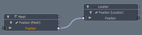
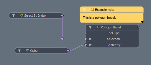
You create links between node connectors with a line representing their association. Once connected, node layouts are referred to as a node graph. There are two types of connectors that can be linked in the Schematic view between nodes: channel links, represented by circles, and relationship links, represented by diamonds.
Channel links are similar to pipes with data flowing from the Output connector of a node (the right-side connection) to the Input connector of the Target (the left-side connection). Relationship connections are different in that they represent a link between the two nodes. Channels can only be connected to channels, and relationships can only be connected to relationships. When you're connecting two channels with different data types, for instance, an Angle channel to a String, Modo converts the source data to the target data type automatically. Modo only allows correct connections to reduce errors.
To create a link between connectors, click any connector and drag to its intended target connector to create a line (often referred to as a 'noodle'). If the link is legal, the line turns green when you move the pointer over the target. Illegal connections change to red. For all legal connections, releasing the mouse button creates the link between connectors. If the line turns yellow, that line replaces the connection. You can create multiple node links simultaneously by pressing the Shift key to select multiple channels and then pressing Shift again while dragging one of the selected channels to its target.
You can move existing node links by clicking either end of a link and dragging the line to a new target. Selecting any link before creating a new item automatically links the element to the selected link.
To remove a link, hold Shift and click the link, or select the link and press the Delete key. To remove all links at a connection, hold Shift and click the connection.
You can disable links by selecting them and pressing the H key. The link turns red, marking it inactive. To enable it again, press the U key. To disable all links connected to a node, select the node and press H. If you press H with no selection, all links are disabled.
You can select a node and all its incoming nodes by right-clicking the node, then in the context-menu, clicking Select Inputs.
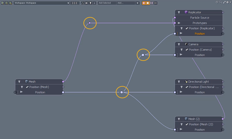
Often, Modo generates a link automatically, for example when creating simple particle simulations. When you add any pre-linked elements to the Schematic viewport, connectors with linked elements not present in the view show with a yellow outline signifying the hidden (minimized) connection. You can make the connected element visible by double-clicking the outlined connector.
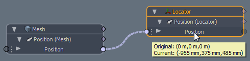
When working with existing links, you can move the pointer over a channel row to see the original and current (driven) values for that connector. By doing this, you can see the current value for the channel itself and see the computed value produced by any linked elements. Moving the pointer over an existing link's line displays it in the foreground with a tooltip showing the connected node's icons on channel row for the channel's type (scalar, vector, matrix, or string). You can also edit node names and channel values by clicking the name or value and typing new information inline.
Workspace and Assembly Navigation
There are two view types in the Schematic viewport: workspaces and assemblies. A workspace is the main area where you create and work on node graphs. You can also experiment and examine existing scene setups. Only a single node graph can be visible at any time in a Schematic viewport. The visibility is determined by the view navigation buttons in the upper part of the viewport. You can create and view as many separate workspaces as desired and compartmentalize them in hierarchies as necessary for organizing scenes. You can extract any node graph or portion of a node graph created within a workspace into an individual assembly. You can view assemblies and navigate them in the same way as you do with workspaces.
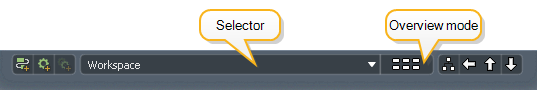
You can open the Selector list (the wide button) to select from the currently available workspaces and assemblies. When opened, the list shows all the root level workspaces and assemblies defined in the scene.
Note: Child assemblies or workspaces are only visible within their own hierarchies.
By selecting the desired workspace or assembly, you see the node graph as the active graph in the viewport. You can create new workspaces and assemblies and navigate and define hierarchies for multi-workspace and assembly setups by using the buttons next to the Selector list.
Clicking the button with the six small white boxes switches the view to Overview mode. This view shows all the workspaces and assemblies in the current scene. Here you can define hierarchies by dragging any workspace or assembly onto that of another to make it a child of the item it is dragged to. Assemblies and workspaces that have a hierarchy beneath them show a small hierarchy badge icon in the lower-right corner of their Overview node graphic. This icon indicates that it has child workspaces or assemblies.
![]()
You can also navigate to any existing workspace or assembly from this view by double-clicking a workspace or assembly node to make that workspace (or assembly) the active workspace.
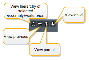
You can navigate hierarchies of workspaces or assemblies directly with the arrow buttons to the right of the Selector list. The first button displays a hierarchy layout of the current active workspace or assembly. With this view, you can see how workspaces and assemblies relate and can double-click to make any node active in the viewport. Clicking the Left arrow navigates back to the last view. Clicking the Up arrow shows the parent item and the Down arrow shows the child item. (You can also use keyboard shortcuts: Alt+Up/Alt+Down arrow keys and Alt+Left/Alt+Right arrow keys to navigate between sibling nodes in a hierarchy.)
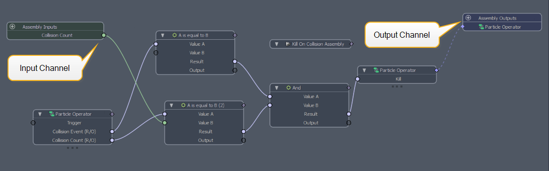
You can use assemblies to package up parts of a graph into a single node and to simplify a node layout graph or as a way to create re-usable assets within a scene (or as a preset to place in other scenes). You can view the contents of any assembly (or sub-assembly) by double-clicking it within the workspace or the Overview view. Doing this shows the contents of the assembly, which is identified by the darker background and the input/output channels. The input/output channels are located on either side of the graph and are color coded: green for input and purple for output. Clicking the + (plus) icon in these areas creates a new user channel on the assembly as additional inputs or outputs to the assembly's contents.
The buttons on the top right of the viewport allow you to manipulate the visibility of different connections.
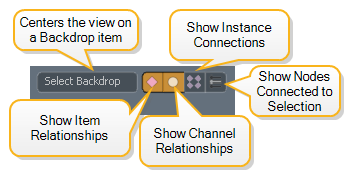
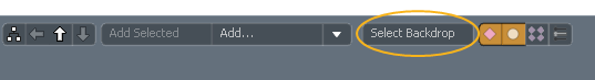
Clicking Select Backdrop focuses in on the selected Backdrop node. For more information on Backdrops, see Backdrop Nodes.
By default, the Schematic viewport shows connections between both items and channels (the links to diamond and circle shaped connectors, respectively). See Defining and Editing Node Links for more information on connections. Clicking the Show Item Relationships button hides or displays connections between items, and clicking Show Channel Relationships hides or displays connections between channels.
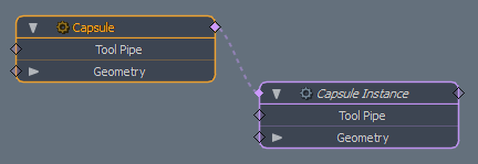
The Show Instance Connections button displays connections between an instance and its source when the instance is selected. For more information on using instances, see Instances.
In complex layouts it can be difficult to see a specific network. In such cases you can use the Show Nodes Connected to Selection button to hide everything that is not directly connected to a selected node.
Note: If no node is selected, Modo displays the whole node graph.
Instancing and Mirroring Assemblies
By instancing assemblies you create multiple copies of a setup (or rig) without needing to duplicate the entire contents of the assembly or without having to manually update all the copies if the original assembly changes. You identify which items are inputs and which are outputs in the original assembly. For example, a suspension rig might have a root item that's parented to the chassis as an input and the hub or wheel as an output. When you instance an assembly, Modo only instances the items marked as inputs or outputs. (Creating replicas for certain items is an option.). You can also mirror an assembly. (For example, you could create a suspension setup and have the other side of a car automatically mirrored. Modo propagates any changes to the original setup to the mirrored Instance.)
To instance an assembly, either right-click the assembly node within a workspace or within the Overview and choose Instance. This creates an instanced duplicate of the items in the Items list, but the node itself has a bracketed number reflecting the number of instances (such as MyAssembly [+3] for three instances). Double-clicking the assembly opens it and, along the bottom of the viewport, the instances show as numbered assembly nodes. To specify how to mirror the assembly, right-click the specific instance and choose Mirror > how to mirror the assembly. Modo mirrors the assembly as directed, such as which axis to use and whether to mirror over the Local (center position) axis or the World position (origin) axis.
Assembly Inputs and Outputs
Inputs are the items or channels that drive the inner workings of the assembly. Most often these are the items that you manipulate to control the rig and the items that you use to position and orient the rig within the scene (such as an assembly root item). An instanced assembly that has no defined inputs is a direct copy of the Source assembly, and it 'sits' directly on top of its source in the 3D views. Any motion on the Source assembly is mimicked in its instances. You use the inputs to establish independent behavior with the instanced assemblies. For example, by assigning the root item of an assembly as an input, you can have all the assembly's instances be positioned independently in the scene.
Another example would be assigning the IK goal of an IK chain as an input and, therefore, allowing all the instances to be controlled independently. You can assign items as an input by right-clicking the item node header and choosing Assign Item as Input. You can also assign individual channels as inputs for an assembly by right-clicking the channel and choosing Expose Channel. This creates a new user channel of the same type, adds it to the assembly Group Item, and assigns a channel link made to the selected channel. Also, by doing this, you can have assembly groups used as sub-assemblies (or black boxes), where internal processes are controlled by a few input/output channels. Alternately, channels can be exposed as inputs by dragging and dropping one or more channels directly over the plus sign icon of the Assembly.
The outputs in an assembly are items that are driven (either directly or indirectly) by the assembly, and are instanced and visible in the 3D views. Mesh items default as outputs in an assembly; you can assign other items to outputs by right-clicking the item node header and choosing Assign Item as Output. Doing this adds an instance of that item to each of the assembly instances in the scene. You cannot manipulate output items in the instanced assemblies directly (for example, by using the Transform tool); however, output items inherit animation from their Source items.
An item cannot be both an input and output for an assembly. Items assigned as outputs cannot be manipulated in any instances of the assembly; however, if you add one or more of the transform items for the output as inputs to the assembly, then FK manipulation, channel linking, and so forth do work.
Tip: Assembly root items are special locators to help keep the items in an assembly organized and that make the assembly easier to manipulate in the acene (especially when working with instanced and mirrored assemblies). Parent any items within the assembly to this root element. You can create an assembly root item within a workspace or an assembly by right-clicking and choosing Create Assembly Root Item or by right-clicking the node header for an existing locator and choosing Assign as Assembly Root Item. Assembly root items are colored, so they are easy to identify within the Schematic view.
Viewport Options
You can find the options that control what elements are displayed in the viewport by clicking the Options icon (the gear icon in the upper-right corner of the viewport). In the Options panel, all options are toggles. A checkmark indicates that the function is enabled, no checkmark indicates that the function is disabled.
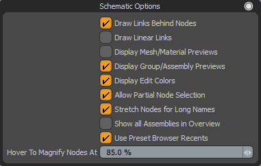
| Draw Links Behind Nodes | When enabled, the resulting link lines are drawn behind the node panels. You can move the pointer directly over an individual connection line to temporarily make it visible in front of the node. When disabled, the lines always appear in front of the nodes. |
| Draw Linear Links |
When enabled, links are drawn as straight lines rather than curves. This aids visibility in more complex scenes. |
| Display Mesh/Material Preview | When enabled, a quick preview icon displays in the header of the node panel for meshes and materials. When disabled, no icon displays. |
| Display Group Assembly Preview |
When enabled, a quick preview icon displays in the header of the node panel for groups and assemblies. When disabled, no icon displays. |
| Display Edit Colors | When enabled, editing colors for items display as node panel outlines. When disabled, the outline colors do not display, but the Items list still shows colored item layers. |
| Allow Partial Node Selection | When enabled and doing a marquee selection of nodes in the Schematic view, the marquee need only touch the node to select it. When disabled, the marquee must completely surround the node to select it. |
| Stretch Nodes for Long Names | When enabled, the the node panels widen to accommodate long names. When disabled, node names are truncated to fit the standard node width. The long name is always visible in the tooltip. |
| Show all Assemblies in Overview | When enabled, all assemblies in the scene are visible in the Overview and not just the assemblies at the root level. When disabled, only the root level assemblies are visible in the Overview. |
| Use Preset Browser Recents |
When enabled, the Add Items menu at the top of the Schematic viewport is replaced by a menu containing items recently added from the Preset Browser.
|
| Hover to Magnify Nodes At | Controls the zoom level of the auto-magnify function to make it easier to work on complex node graphs. When the viewport is scaled at or below 85% (the default value), moving the pointer over the scaled node temporarily enlarges it to 100%. This is useful when dragging connectors from one side of a graph to another. Zoom out and move the pointer over the Source node. When scaled, click the channel hub to initiate the link and then drag to the Target node. When the pointer is over the Target node, it too scales for you to see a full-sized view to connect the channels. (This also works with multiple links if you press the Shift key to select the channels.) |

Shortcut Menus
The Schematic viewport has a variety of shortcut menus to use when you right-click a specific element. Depending on what element you click, you see a different menu with commands specific to that task.
Right-clicking an empty area of the workspace or assembly background opens this menu.
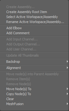
Create Assembly: Opens the Schematic Create Assembly dialog to package the selected node(s) into a single assembly node that simplifies the graph and makes the setting more portable for re-use elsewhere. You can double-click the resulting assembly to view and edit its contents.
Create Assembly Root Item: Creates a special locator item that you can assign as the parent in a hierarchy to the items in an assembly. It becomes the root of all the elements within. This makes the elements easier to manipulate in the 3D viewport — especially when working with instanced and mirrored assemblies. This must be assigned as an input item. Modo draws the assembly root item in the Schematic viewport with a green indicator and in the 3D viewport as a green box for easy identification.
Select Active Workspace/Assembly: Selects the active workspace or assembly in the Groups palette. Modo indicates all related elements to denote its selected state.
Rename Active Workspace/Assembly: Opens a dialog for you to rename the current active workspace or assembly. Once changed, the name is visible in the various menus and in the Overview view.
Add Elbow: Adds an elbow node to the scene. Elbow nodes can be placed on a link to reduce visual clutter in complex scenes. You can add elbows in a number of other ways:
• Right-click a link and then click Add Elbow.
• Double-click a link.
• Select the link and press . (period) on the keyboard.
In addition to changing the shape of a link, you can also use them to group several links together. Select the links to add, and press . (period) on the keyboard. You can drag additional links to an elbow.
To delete an elbow, select it and press Delete on the keyboard.
Add Comment: Adds a Comment node that allows you to leave notes anywhere in the Schematic. You can also add a comment by pressing Alt+n on the keyboard. For more information, see Adding Comments.
Add Input/Output Channel: Opens the Add User Channel dialog and connects the resulting channel as an exposed input or output to the assembly.
Add User Channel: Opens the Add User Channel dialog for you to create custom channel types that can be connected for various rigging purposes. See the Add User Channel topic for more details.
Update All Thumbnails: Forces Modo to refresh all node icons and to update them to their current states if they have changed. You must have Display Mesh/Material Preview enabled as a viewport option to see icons on nodes.
Backdrop: Adds a backdrop node. Backdrop nodes help you to organize complex scenes by grouping several nodes together. For more information, see Backdrop Nodes.
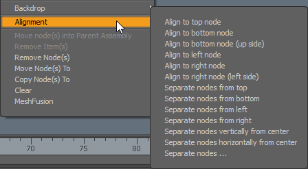
Alignment: You can use various alignment options to arrange the nodes in your scene. In the viewport, select the nodes to align, right-click, and choose one of the alignment options. You can also use keyboard shortcuts. For more information, see Aligning Nodes.
Move Node(s) into Parent Assembly: Moves one or more nodes from the current assembly to its parent.
Remove Item(s): Removes the selected item(s) from the scene.
Remove Node(s): Removes the selected nodes(s) from the Schematic viewport.
Move Node(s) To: Moves all selected elements to the specified location in the sub-menu. The sub-menu lists all the current workspaces and assemblies.
Copy Node(s) To: Copies the selected node(s) to the specified location in the sub-menu. The sub-menu lists all the current workspaces and assemblies. The copied nodes still reference the same initial Source item and changes made in the copy are reflected in the original node because both nodes reference the channels from the same source item. (The item itself is not being cloned, only its representation.)
Clear: Removes all nodes from the workspace or assembly. This command essentially resets the viewport to its initial, empty state.
MeshFusion: Options for manipulation MeshFusion nodes.
Right-clicking a link connection line opens this menu.
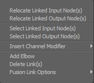
Relocate Linked Input/Output Nodes(s): Autopositions the node within the Schematic viewport for the incoming or outgoing link(s).
Select Linked Input/Output Node(s): Automatically selects the nodes of the incoming or outgoing links.
Insert Channel Modifier: Adds the specified channel modifer to the schematic graph. The submenu lists all the Channel Modifiers that can be added.
Add Elbow: Adds an elbow node to the scene. Elbow nodes can be placed on a link to reduce visual clutter in complex scenes. You can add elbows in a number of other ways:
• Right-click in the Schematic viewport, then click Add Elbow. This adds an elbow that's not part of any link.
• Double-click a link.
• Select the link and press . (period) on the keyboard.
In addition to changing the shape of a link, you can also use them to group several links together. Select the links to add, and press . (period) on the keyboard. You can drag additional links to an elbow.
To delete an elbow, select it and press Delete on the keyboard.
Delete Link(s): Removes the connector line between nodes and eliminates the link.
Fusion Link Options: Options to manipulate MeshFusion links.
Right-clicking a node header (title) opens this menu.
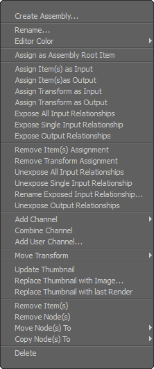
Create Assembly: Opens the Schematic Create Assembly dialog to package the selected node(s) into a single assembly node that simplifies the graph and makes the setting more portable for re-use elsewhere. You can double-click the resulting assembly to view and edit its contents.
Rename: Makes the name of the Target assembly editable inline.
Editor Color: Defines a layer color for identifying and organizing items. This shows in the Schematic viewport as a colored outline around the node panel.
Assign as Assembly Root Item: Converts an existing locator item into an assembly root item locator. This is a special kind of locator that you can assign as the parent in a hierarchy to the items in an assembly. Therefore, it becomes the root of all the elements within. This makes the elements easier to manipulate in the 3D viewport — especially when working with instanced and mirrored assemblies. This must be assigned as an input item. Modo draws the assembly root item in the Schematic viewport with a green indicator and in the 3D viewport as a green box for easy identification.
Assign Item(s) as Input: Assigns one or more of the items within an assembly as an input for you to control which of the items within the assembly are instanced with the assembly (appear in the Items list as instances). You can independently transform items designated as inputs as instances (relative to their root).
If you defined the assembly root item as the input, by using this command you can position the instanced assembly independently of its source. If you define additional items as inputs, they appear in the Items list, and you can select them and transform them independently as well (relative to their root).
Assign Item(s) as Output: Assigns one or more of the items within an assembly as an output for you to control which of the items within the assembly are instanced with the assembly (appear in the Items list as instances). Mesh items default to being outputs. Items designated as outputs cannot be independently transformed in the resulting instances, but are driven by the Source item and duplicate its transforms. If parented to a hierarchy under an assembly root item, the instanced item transforms relative to the root's position (if the root is defined as an input).
Assign Transform as Input/Output: Allows selected transform channels (such as position, rotate, and scale) to be designated as inputs or outputs independently of the item's designation.
Expose Input/Output Relationship: Exposes a relationship connector on a node within the assembly so it can drive or be driven from outside the assembly.
Remove Item Assignments: Removes any input or output assignment applied to an item.
Remove Transform Assignments: Removes any transform input or output assignment applied to an item's transform channels.
Unexpose Input/Output Relationships: Removes an exposed relationship and prevents the channel from driving or being driven from outside the assembly.
Add Channel: Opens a menu with all the un-added channels for the associated item for you to add additional channels to the node without having to drag them or select them in the Channels viewport.
Combine Channel: Moves all selected channels for the selected item from their original nodes into the recently selected node.
Add User Channel: Opens the Add User Channel dialog for you to create custom channel types that can be connected for various purposes. See the Add User Channel topic for more details.
Move Transform: Changes the order of the selected Target transform channel (for items that have related transforms) as indicated in the the submenu.
Update Thumbnail: Forces Modo to refresh the thumbnail image. You must have the Display Mesh/Material Preview viewport option enabled to see icons on nodes.
Replace Thumbnail with Image: Opens an OS-specific dialog for you to select a saved image to replace the current icon representing the node. If the selected image is larger than 128x128, Modo resamples it to that size.
Replace Thumbnail with last Render: Replaces the current icon image with the last render in the Render list of the Render Display viewport. Modo must have created the render during the current session. If the rendered image is larger than 128x128, Modo resamples it to that size.
Remove Node(s): Removes the selected nodes(s) from the Schematic viewport.
Move Node(s) To: Moves all the selected nodes to the specified workspace or assembly. The submenu lists all the current workspaces and assemblies.
Copy Node(s) To: Copies all the selected elements to the specified location. The submenu lists all the current workspaces and assemblies.
Delete: Removes the node and its associated item from the scene.
Right-clicking a node header (title) for an assembly opens this menu.
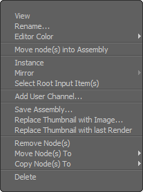
View: Switches to view any selected assembly.
Rename: Makes the name of the Target assembly editable inline.
Editor Color: Defines a layer color for identifying and organizing items that display in the Schematic viewport as a colored outline around the node panel.
Move node(s) into Assembly: Move the selected node(s) into the selected assembly.
Instance: Creates a virtual copy of an assembly (which references its master assembly) that can be used elsewhere in a schematic graph, workspace, or assembly. You can only apply this command to an assembly node from the workspace or in the Overview view.
Mirror: Inverts an instanced assembly across the user-defined axis specified in the submenu. This is useful for making multiple identical items that mirror (such as the wheels of a car or the IK leg setup of a spider). The submenu lists the Local axis (the root item's center point) or the World axis (World Origin). If there is an assembly root item in the assembly, then Modo uses its location and orientation as the mirror axis.
To mirror an assembly, you must instance it first. Then, by opening the root assembly (double-click the assembly in the Overview view), the individual instances appear in a new section toward the bottom of the viewport. By right-clicking the Target instance, you can then choose Mirror. Once you assign mirroring, you can position the resulting mirrored assembly by using the exposed channels or by positioning the root locator.
Select Root Input Item(s): Selects all locator items in the assembly that are assigned as inputs and that have no parent present in the assembly.
Add User Channel: Opens the Add User Channel dialog for you to create custom channel types that can be connected for various purposes. See the Add User Channel topic for more information.
Save Assembly: Opens an OS-specific dialog for you to save the assembly as a preset. If saved to the Presets directly, you can then later drag the resulting assembly preset from the Preset Browser directly into a new scene.
Replace Thumbnail with Image: Opens an OS-specific dialog for you to select a saved image to replace the current icon representing the node. If the selected image is larger than 128x128, Modo resamples it to that size.
Replace Thumbnail with last Render: Replaces the current icon image with the last render in the Render list of the Render Display viewport. Modo must have created the render during the current session. If the rendered image is larger than 128x128, Modo resamples it to that size.
Remove Node(s): Removes the selected nodes(s) from the Schematic viewport.
Move Node(s) To: Moves all the selected nodes to the specified workspace or assembly. The submenu lists all the current workspaces and assemblies.
Copy Node(s) To: Copies all the selected elements to the specified location. The submenu lists all the current workspaces and assemblies.
Delete: Removes the assembly from the scene and all items contained in it.
Right-clicking a node connector dot opens this menu (for both input and outputs).
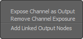
Expose Channel as Input/Output: Makes the selected channel visible on the assembly node so you can link other external nodes to it.
Remove Channel Exposure: Hides exposed channels so they are no longer visible on the assembly node.
Add Linked Output Nodes: Finds any nodes that are linked to the selected channels or relationships and brings them into the current workspace or assembly.
Right-clicking any channel inside a node panel opens this menu.
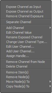
Expose Channel as Input/Output: Makes the selected channel visible on the assembly node so you can link it to other external nodes.
Remove Channel Exposure: Hides exposed channels so they are no longer visible on the assembly node.
Separate Channel: Separates the channels out from a node to their own node panel that can be positioned independently for easier graph construction. Modo draws three small dots under both node panels to indicate the separated state.
Add Channel: Opens a menu that allows you to select from any of the items available channels and add them to the node directly when selected.
Edit Channel Value: Makes the channel value of editable inline.
Rename Exposed Channel: Makes the user channel name editable inline.
Change User Channel Types: Opens the Change Channel Type dialog to change the type of a user channel (for example, changing a Scalar channel to a Boolean channel).
Edit User Channel: Opens a form for editing the properties of a user channel's definition.
Add User Channel: Opens the Add User Channel dialog for creating a custom channel type that you can connect for various purposes. See the Add User Channel topic for more information.
Assign Handle: Works in conjunction with the Channel Handles function to assign the selected channel to the appropriately created handle. See the Channel Handles page for more information.
Remove Channels from Node: Removes the channels from the channel row of the node panel, but the channels are still active within the Channels viewport of the related Item.
Delete Channel: Removes the user channels for the selected item.
Remove Item(s): Removes the selected item(s) from the scene.
Remove Node(s): Removes the selected nodes(s) from the Schematic viewport.
Move Node(s) To: Moves all the selected nodes to the specified workspace or assembly. The submenu lists all the current workspaces and assemblies.
Copy Node(s) To: Copies all the selected nodes to the specified workspace or assembly. The submenu lists all the current workspaces and assemblies.
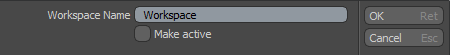
![]() Create New Workspace: Clicking this button opens the New Schematic Workspace dialog where you can create and name the new empty workspace. You can also define whether you want it to become the currently active workspace. In a new scene, if there is nothing in the active workspace when you create a new workspace (an empty workspace), the newly created workspace becomes the initial workspace. All other new workspaces thereafter are in addition to the initial workspace.
Create New Workspace: Clicking this button opens the New Schematic Workspace dialog where you can create and name the new empty workspace. You can also define whether you want it to become the currently active workspace. In a new scene, if there is nothing in the active workspace when you create a new workspace (an empty workspace), the newly created workspace becomes the initial workspace. All other new workspaces thereafter are in addition to the initial workspace.
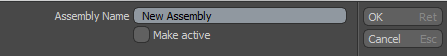
![]() Create New Assembly: Clicking this button opens the New Schematic Assembly dialog where you can create and name a new empty assembly and specify it to be the currently active assembly for editing.
Create New Assembly: Clicking this button opens the New Schematic Assembly dialog where you can create and name a new empty assembly and specify it to be the currently active assembly for editing.
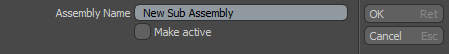
![]() Create New Sub-Assembly: Clicking this button opens the New Schematic Sub-Assembly dialog where you can create and name a new empty sub-assembly (a child in the hierarchy of the currently active assembly). You can define whether you want it to be the currently active assembly for editing.
Create New Sub-Assembly: Clicking this button opens the New Schematic Sub-Assembly dialog where you can create and name a new empty sub-assembly (a child in the hierarchy of the currently active assembly). You can define whether you want it to be the currently active assembly for editing.
Creating Assemblies from a Graph
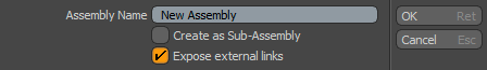
Once you have a working graph or even a portion of a graph set up, you can create an assembly from it. Assemblies are useful to simplify very complex graph layouts by compartmentalizing multiple nodes into a single node. You can also create assemblies to separate parts of a graph for organization to be able to work on each area independently. You can also treat assemblies as assets to save and re-use later. To create an assembly, in the graph select each of the nodes that you want to include. Then right-click a blank area of the background and choose Create Assembly. In the Schematic Create Assembly dialog, provide a name. You can create an assembly as a normal assembly or as a sub-assembly. To create a sub-assembly, select the Create as Sub-Assembly checkbox. (The new sub-assembly becomes part of the current graph; otherwise, Modo creates a standalone root level assembly.) In both cases, Modo removes the selected nodes from the graph and adds them to the new assembly. To create channels on the new group for each channel link to or from a channel within the group, select the Expose External Channels checkbox. (It is only applicable to sub-groups and is useful for creating assemblies that can be re-used elsewhere — a black box that you can connect without knowing about the internal processes.) Click OK to create the new assembly. If it was a standalone assembly, the view changes into the Assembly view to show its contents.
Creating Sub-Assembly Walk-through
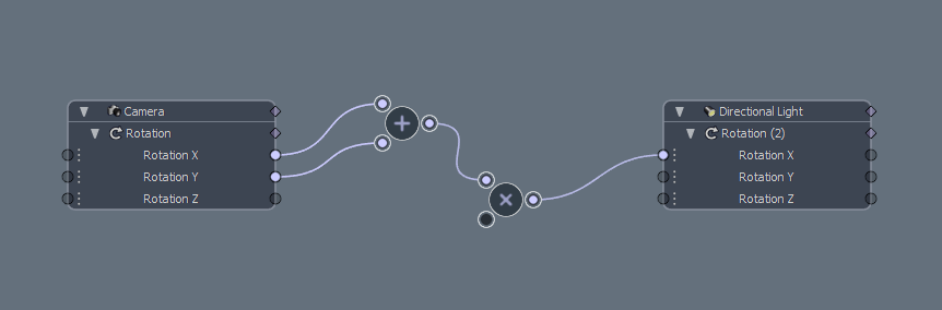
Select the elements that make up the sub-assembly. This shows the + (add) and x (multiply) nodes.
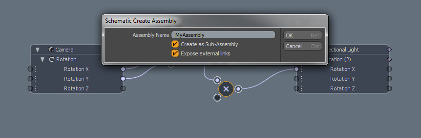
Right-click an open area of the workspace and choose Create Assembly.

Clicking OK changes the selected elements into the sub-assembly.
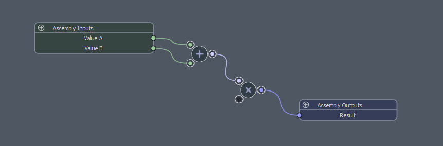
You can view the contents of any sub-assembly by double-clicking the named assembly node.
Note: Within the scene's file structure, Modo stores the actual data for schematic graphs in a special group type in the Groups viewport. Within that viewport you can see the options for assemblies. These are the same groups that show in the Assembly mode of the Schematic viewport. You can create new assemblies by using the New Group button. Using this button creates a new blank display in the schematic. The schematic always shows the most recently selected assembly. (You cannot create workspaces, although viewable, within the Groups viewport.).
Note: The concept of using the Schematic viewport is easy enough to understand for creating links from one node to another, but the concept of rigging and animation control building overall is very complex.
Backdrop Nodes
Courtesy William Vaughan
Backdrop nodes help you to organize complex Schematic networks by grouping several nodes together.
To add a Backdrop, select your nodes, right-click in the viewport and click Backdrop > Create Backdrop. Alternatively, select your nodes and press B on the keyboard.
To add additional nodes to the group, select the node and the Backdrop, right-click in the viewport and click Backdrop > Add Item(s) to Backdrop. Alternatively, select the node, hold Shift and drag it into the Backdrop.
To remove a node from the Backdrop, do either of the following, select the node, right-click in the viewport and click Backdrop > Remove Item(s) from the Backdrop, or select the node, hold Shift and drag it out of the Backdrop.
Tip: You can also create Backdrops within Backdrops. This can be useful for example in procedural modeling, when you want to isolate a set of mesh operations.
To move a Backdrop, simply click on its header and drag it to the required position in the viewport.
Backdrops can be colored too, to make them easier to see. To assign color to a Backdrop node, right-click the node and in the context menu under Editor Color, click the color you need.
To focus the view on a single Backdrop node, click Select Backdrop at the top of the viewport and select the Backdrop from the list.
Aligning Nodes
With complex scenes, you may need to arrange your nodes more clearly. Modo's alignment and separation commands can help you to create a better-organized scene.
In the Schematic, select the nodes to align, then use the required keyboard shortcut:
Right-click in the viewport, and in the context menu, select Alignment, then click the option you need.
| Align Commands | |
| Align to top node | Up Arrow |
| Align to bottom node | Down Arrow |
| Align to bottom node (up side) | Shift+Down Arrow |
| Align to left node | Left Arrow |
| Align to right node | Right Arrow |
| Align to right node (left side) | Shift+Right Arrow |
| Separate Commands | |
| Separate nodes from top | Ctrl/Cmd+Alt+Down Arrow |
| Separate nodes from bottom | Ctrl/Cmd+Alt+Up Arrow |
| Separate nodes from left | Ctrl/Cmd+Alt+Right Arrow |
| Separate nodes from right | Ctrl/Cmd+Alt+Left Arrow |
| Separate nodes vertically from center | Ctrl/Cmd+Alt+Shift+Up/Down Arrow |
| Separate nodes horizontally from center | Ctrl/Cmd+Alt+Shift+Left/Right Arrow |
Adding Comments
Courtesy William Vaughan
Note: The keyboard shortcut for adding a comment node has been changed to Alt+N.
You can add comments in the Schematic using the Comment node.
You can add a comment in the following ways:
• Right-click in the Schematic viewport and click Add Comment.
• Press Alt+n on the keyboard.
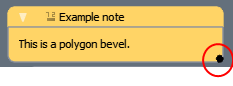
To rename your Comment node, click the title. The field becomes editable.
To resize the Comment node to accommodate your text, click the black circle in lower right corner and drag the box to the required size.
Editing Channel Values on a Node
You can edit a channel's value on a node by clicking on it in the Schematic. Depending on the type of channel, you have different ways of editing the channel:
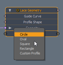
• When different text options are available, you can select the option you need from a dropdown.
• For colors, this opens Modo's default Color Picker.
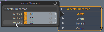
• For vectors, this opens the Vector Channels form.
• For gradients, this opens the Gradient Editor.
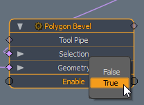
• For Boolean toggles, such as the Enable channel on a Mesh Operation, use a simple True/False popup.
• For other channel types, you can use the inline editor to type in a value.