Bezier
The Bezier tool allows you to create a type of curve defined by off-curve control handles. Bezier curves were originally developed for computer modeling in automotive design, but are popular in many vector drawing applications. These curves provide a familiar means of generating curves, as they allow you to interactively control the amount of incoming and outgoing curvature for each control point.
You can find the Bezier tool in the Create sub-tab of the modeling toolbox and in the menu bar under Geometry > Curve Palette.
To use the tool:
| 1. | In the Create sub-tab of the modeling toolbox, click the |
Alternatively, you can access the tool in the menu bar under Geometry > Curve Palette.
| 2. | Click in the 3D viewport to position the first control point, then continue to drag the mouse cursor to create the Bezier handle. |
| 3. | Release the mouse button to set the handle length. |
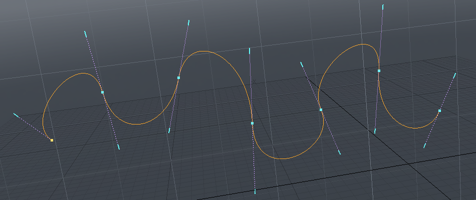
Subsequent clicking and dragging draws additional control points and handles with a curve segment between each control point. Control points are always created at the intersection of the work plane and the mouse button click. The curvature of the segments between control points is defined by the Bezier handles, which are called endpoint tangent vectors.
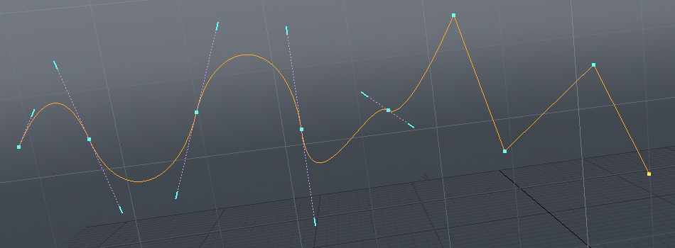
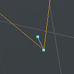
| 4. | To create straight line segments, click in the viewport without dragging. This creates control points with zero-length tangents. When you move these control points later, the corners remain sharp and the lines straight. You can see the two control point types below: |
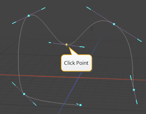
| 5. | You can smooth sharp corners by switching to Edit mode in the Bezier tool's Properties panel. Edit mode reveals handles for the control points that you can drag out to create round corners: |
| 6. | While the tool is active, you can re-position the control points by clicking and dragging them. Holding Shift and moving a point affects all points downstream of the selected control point as a single unit. |
Note: Point order is defined by the initial order in which the curve was created. Press F before activating the tool to invert the order.
Tip: To create a closed curve, right-click on the first control point. Modo adds a curve segment between the first and last control points.
Points always move on the two axes relative to the current work plane, so rotating the viewport to change an axis may be necessary.
You can edit the handles in a similar way. Dragging on the end of one handle breaks tangency, allowing opposing handles to be different lengths and/or angles. You can restore tangency and edit both handles in unison by pressing and holding Shift while adjusting the handles.
| 7. | You can add points to a curve using the Add and Insert modes: |
• Add always creates a control point relative to the currently selected point on the curve and warps the curve to accommodate the new point.
• Insert creates a control point on the curve closest to the click-point and does not warp the curve.
|
|
|
|
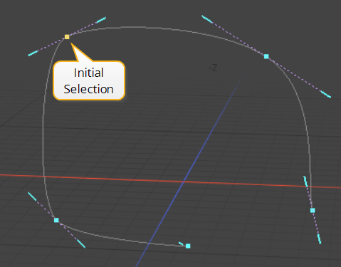
The initial bezier shape and control point selection |
|
|
|
|
|
Add mode creates a point and warps the curve |
Insert mode creates a point on the existing curve |

| 8. | Delete mode removes the selected point and warps the curve to accommodate the change. |
Bezier Tool Properties
Once you drop the tool by pressing the spacebar, interactive handle editing within the tool itself is lost but you can re-activate the editing ability by selecting the curve in Polygons selection mode. This displays the editing handles. Control points along the Bezier curve can also be positioned precisely by selecting the target vertex and using the Point X, Y, Z fields of the tool's Properties panel.
The following Bezier options are available for adjusting the Bezier tool:
|
Bezier |
|
|---|---|
|
Mode |
There are four Bezier curve mode options: • Add - The default mode. Creates a control point relative to the currently selected point on the curve and warps the curve to accommodate the new point. • Edit - Click and drag any of the control points or handles along the curve to change the look to the desired shape. Pressing and holding the Shift key allows you to edit both handles of a control point simultaneously. • Delete - Click any control point along the curve to remove it from the Bezier. • Insert - Creates a control point on the curve closest to the click-point and does not warp the curve. |
|
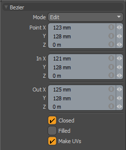
Point X, Y, Z |
You can assign specific X, Y, and Z values in these input fields for the currently-selected control point, allowing for finer point control. |
|
In X, Y, Z/Out X, Y, Z |
You can assign specific X, Y, and Z values in these In and Out input fields for the currently-selected (highlighted) handle, allowing for finer handle control. |
|
Closed |
Adds an automatic curve segment between the first and last control point positions, producing a closed curve. |
|
Filled |
When the Closed option is enabled, you can enable this to create a renderable flat surface defined by the outlining curve. The resulting surface can be tagged like a polygon for adding material definitions. |
|
Make UVs |
Activates auto-generation of UV texture coordinates along the curve. The generated UV values are of a single vertical line (V axis in UV), positioning all the control point vertices evenly between 0 and 1. For example, this can be useful for applying a gradient to a rendered curve. The Render Curves option is available in the Mesh Item properties. |