Mesh Item
Mesh Items are often referred to as geometry layers as this is how they appear in the Item List, as individual layers. However, these layers can also be thought of more like containers that hold the various geometry components - vertices, edges, and polygons. Mesh Items are usually the heroes of any project; the actual surfaces that are rendered. Each individual mesh layer is its own self-contained object, with its own set of channels, item transforms, as well as UV maps, Weight Maps, and any other associated Vertex Maps.
Mesh Items are animated by transforming their position, rotation and scale channels, or by using Deformers to bend and twist the geometry contained within. Component-level changes modify the contents contained within the layer, and can generally be applied independent of the animation assigned to the item. The difference between component edits and Item-level edits is a very important concept to understand. If you ever find that you have performed Item-level transforms when you intended to do component transforms, you can use the Freeze options found on the item's Properties panel to return the center location back to the World Origin.
You can add additional Mesh Items to a scene by pressing the Add Item button at the top of the Item List and selecting Locators > Mesh. Additionally, you can use the menu bar command Geometry > New Mesh Item. Finally, you can also easily create an empty mesh layer by simply pressing the N keyboard shortcut while in the Model interface layout. When the Mesh Item is selected, its associated attributes become available for selection and you can edit it within the Properties viewport panel.
Mesh Tab
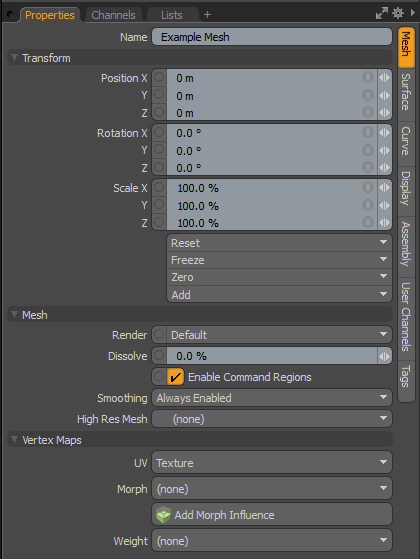
• Name - displays the current item name. You can easily change it by clicking within the field and typing the new name.
Note: Please be aware that currently you cannot have multiple Mesh Items that share the same name and that Item names need to be unique to the item. Mesh items that share the same name will automatically be versioned to reflect the amount of items in your scene that share the naming convention; for example if your scenes contains three items all named Cube, the first mesh item created will be named Cube, while the two subsequent Cube items will be named Cube (2) and Cube (3).
The following Transform options are available for the Mesh Item:
• Position - an item transform that allows you to numerically position the item in XYZ space. By default, Position transforms originate from the item's Center position.
• Rotation - an item transform that allows you to numerically set the rotation of the item. By default, Rotation transforms originate from the item's Center position.
• Scale - an item transform that allows you to numerically set the size of the item. By default, Scale transforms originate from the item's Center position.
• Reset - resets the selected transform values to (0,0,0) returning the items back to their default state.
• Freeze - returns the item's Center position to the world space center (0,0,0) without changing the position of the Mesh Item itself.
• Zero - resets the chosen transform property values to 0, leaving the Center position and mesh position intact. This is done by adding an additional transform item to the Mesh Item's channels with an inverted version of the current values. This is useful to allow, for example, a joint to have a base value of 0,0,0 but still be located away from the World Origin.
• Add - adds additional Transform items to the associated item or, if they do not yet exist, it simply adds them. Transform items are the channel groups that store the actual transform values controlling any item's position, rotation, and/or scale. You can add as many Transform items as desired for any transform property desired. Adding additional Transform items produce an additive effect where each transform group is evaluated before the next, and so on. Additional item transforms are evaluated in their order in the channels list, from the bottom upwards.
It should be noted that by default, new items do not have any transform items associated with them (even though they are visible here within the Properties panel). This is useful as an optimization, as only the necessary transforms are created on an as-needed basis, reducing scene overhead. There are several actions that add these base transform items. One is by simply transforming the target item with one of the various transform tools or by editing the values input fields. This action causes the particular transform item to be added automatically to the Channels viewport list. Die to this fact, you may need to specifically create item transforms when Referencing, because in order to override the channels in the Master scene, they must first exist.
The following Mesh options are available for the Mesh Item:
• Render - allows you to select from three choices: when set to Default, you can enable/disable Mesh Items using the visibility column (eye icon) of the Item List, when the mesh layer is visible, it contributes to the final rendered scene, and when invisible, it does not. On some instances you may prefer to fix this state, setting the mesh as On (enabled) or Off (disabled), regardless of layer visibility. These controls are also useful for workflows that auto-toggle visibility, saving you from manually enabling mesh layers for test renders.
• Dissolve - controls the visibility of an item layer when rendering. At 0% the item renders normally, utilizing the Shader Tree settings. Values above 0% fade the visibility of the item layer, ramping toward 100%, where the item would be completely invisible.
• Enable Command Regions - can be used to toggle the automatic Command Regions functionality. When enabled, command regions work as defined; when disabled, command region definitions are ignored.
• Smoothing - a performance-enhancing option that allows you to control the Smoothing applied to a Mesh Item on an individual basis. When disabled, the reduced evaluation overhead can be useful to help to increase performance in heavy scenes. Always Enabled smooths the entire layer at all times, Disabled with Deformers disables any smoothing only when a deformer is attached to the item layer, and the last option, Always Disabled, eliminates smoothing for the item at all times.
• High Res Mesh - Specify the mesh item to use for baking a normal map. It can either bake the normal textures applied to the mesh item or do object to object baking. For more information, see Working with Bake Items and Baking Tools.
The following Vertex Maps options are available for the Mesh Item:
• UV - provides a convenient means to select the current UV map that is visible in the 3D Viewports. It also allows the ability to easily create a new map by selecting the New option. For more information, reference the Vertex Maps topic.
• Morph - provides a convenient means to select the current active Morph map. It also allows the ability to easily create a new map by selecting the New option.
• Add Morph Influence - automatically creates a Morph Influence with the selected Morph map, that is connected to the current mesh. Morph deformers are only visible in viewports that have the Enable Deformers option enabled.
• Weight - provides a convenient means to select the current Weight Map that is visible in the 3D Viewports. It also allows the ability to easily create a new map by selecting the New option.
Surface Tab
• Name - displays the current item name. you can easily change it by clicking within the field and typing the new name.
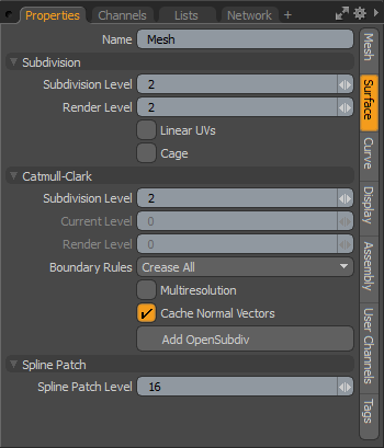
The following are Subdivision options for the Mesh Item:
• Subdivision Level - any selected geometry within a layer can be converted to a subdivision surface by selecting the target geometry and pressing the Tab key, converting the geometry. This produces a smoothing effect to the surface, essentially becoming a proxy for the smoothed SDS geometry, which cannot be directly edited. The Subdivision Level setting specifies to what degree an SDS model is divided. There are certain functions that override this setting at render time, such as those for Adaptive Subdivision. Otherwise, when using the Freezing Geometry command, the Subdivision Level controls the number of polygons generated, as it controls the number of polygons displayed in any 3D viewport. This value can be interactively adjusted with the +/- (plus/minus) keys on the number pad when a Mesh Item is selected.
• Render Level - when Adaptive Subdivision is disabled, you can set an independent Render Level for subdividing the geometry only when any of the Render Commands are invoked. This can be helpful in increasing OpenGL viewport performance by setting a low Subdivision Level and a high Render Level, keeping a finely subdivided smooth surface only when the scene is rendered.
• Linear UVs - Modo automatically switches between linear UVs for straight polygonal geometry and smoothed UVs for subdivision surface (SDS) geometry. There may be some instances where an image map created outside of Modo utilizes linear for an SDS model, in which case enabling Linear UVs correctly applies the image map to the Sub-D geometry within Modo.
• Cage - toggles any Subdivision Surface geometry in the current mesh layer. This is especially useful in temporarily disabling SDS in complex models without losing the SDS definitions for the geometry.
The following are Catmull-Clark options for the Mesh Item:
• Subdivision Level - you can convert any surface into a Catmull-Clark Subdivision Surface by pressing the Shift+Tab keyboard shortcut. The Catmull-Clark Subdivision Surfaces are superior to regular Subdivision Surfaces, especially in their handling of edge creasing. However, they are more computationally intensive than regular Subdivision Surfaces and require more memory to render. The Subdivision Level controls how finely a surface is subdivided.
• Current Level - when the Multiresolution option is enabled, you can use the Current Level option to step up and down through the different levels of subdivision (up to the maximum level defined by the Subdivision Level). This is useful when sculpting, providing the ability to add different degrees of detail to a model at different levels.
• Render Level - when Adaptive Subdivision is disabled, you can set an independent Render Level for subdividing the geometry only when any of the render commands are invoked. This can be helpful in increasing OpenGL viewport performance by setting a low Subdivision Level and a high Render Level, keeping a finely subdivided smooth surface only when the scene is rendered.
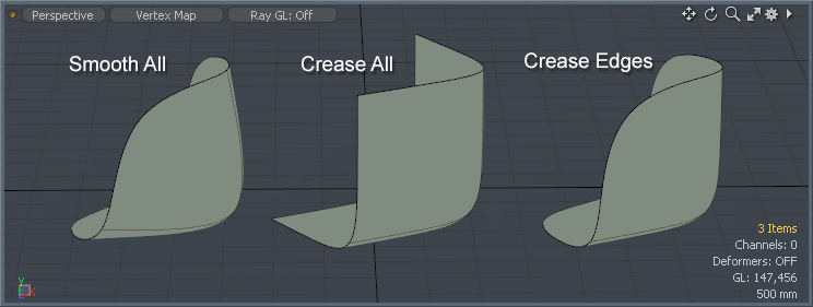
• Boundary Rules - the boundary rules determine how to move the points on the boundaries of a Catmull-Clark Subdivision Surface mesh. Creasing produces a sharper transition between surfaces, while smoothing produces smooth surface transitions. The differences between Smooth All and Crease Edges are only noticeable on modes that use the Edge Weighting function. The options are:
• Smooth All - all positions on the boundary are moved by the smooth rule of Pixar Subdivision Surfaces.
• Crease All - the points that have two incident edges (valence = 2) are moved by the crease rule; other positions on the boundary are smoothed by two boundary edges.
• Crease Edges - the points that have two incident edges (valence = 2) are moved by the smooth rule; other positions on the boundary are smoothed by two boundary edges.
• Multiresolution - only available to a Pixar Subdivision Surfaces model; you can enable this option to step up and down through the subdivision levels when sculpting a mesh, allowing you the ability to add varying degrees of detail without obliterating detain present in other levels. You can adjust the current level using the Current Level option, above, or step through the levels using the Multi-res settings in the sculpting toolbox of the Paint interface tab.
• Cache Normal Vectors - this is useful to enable when sculpting a Multi-resolution mesh. When enabled, normal vectors for the mesh are stored in memory, increasing brush stroke performance. Depending on the system, this increase can be significant. The drawback to the option is that it can increase system memory usage significantly as well, depending on the target mesh's density. On modest systems, the use of the option should be limited to either light meshes or disabled altogether for maximum performance.
• Add/Remove OpenSubdiv - when enabled, replace the standard Modo Catmull-Clark subdivision surfaces display algorithm with the high performance Open Subdiv standard. Pressing the button adds an additional option to the panel allowing you to define which Compute method is utilized. The Add Open Subdiv option is meant as a performance enhancement that can improve playback speeds of deforming Catmull-Clark meshes in the 3D viewport. For general modeling, you should stay with the standard Modo Catmull-Clark setting for best performance. To remove the option, simply press the Remove OpenSubdiv button reverting back to the prior settings.
• Compute - only appears when you have enabled the OpenSubdiv high performance subdivision surfaces standard. There are four possible options:
• Automatic - when defined, it chooses the best mode, based on the current system. GPU mode is the highest priority, if it is available. Multi Threads selection is chosen, if no GPU mode is available. Otherwise, barring those choices, it defaults to CPU mode.
• CPU - when defined, the subdivision is computed by CPU, using the main thread.
• GPU - uses OpenCL framework or GLSL Transform Feedback. If the current computer does not support OpenCL, it chooses another mode.
• Multi Threads - selects one of the multi-threading frameworks like GCD, OpenMP, or TBB. For Mac OS X, GCD is selected for multi-thread mode. TBB is chosen for Windows and Linux, if it is available, otherwise it selects OpenMP.
• Spline Patch Level - spline patching is a way of parametrically defining a surface with a number of curves. When patching the curves to define the surface, the Spline Patch Level controls the number of polygons used. These polygons are not directly editable unless you apply the Freeze command found under the menu bar Geometry > Freeze.
Curve Tab

• Name - displays the current item name. You can easily change it by clicking within the field and typing the new name.
The following Curve Settings options are available for the Mesh Item's Curve tab:
• Render Curves - generally curves are non-rendering items in a layer meant to facilitate other functions: visual aids, patching guides, duplication paths, and so forth. However, with the Curve Radius set to a value above 0, and the Render Curves option enabled, the previously-invisible curves are now renderable. Modo procedurally generates geometry, based on your settings only at render time. Material tags for surfacing can be applied to curves in the same way they are for regular polygons by selecting the curve in Polygons mode and assigning a Material tag to it, as if it were a normal polygon. Then any material settings assigned in the Shader Tree to that material group are applied to the curve at render time.
Rendered curves essentially become tubes that have several benefits over extruded geometry. They reduce the amount of geometry in the scene since render curves are only generated at render time, making for a lighter file size, and their size is editable and animatable as well. Additionally, any morph deformations applied to a curve itself won't impair the final surface, where it keeps a consistent thickness through the deformation.
• Curve Radius Unit - you can define the size of the rendered curve in two ways: using the world unit Meters, which defines the size based within the scene, and using Pixels, which defines the curve based on the rendered image. Using Meters produces a cylinder size that is consistent with the scene itself, and has perspective, scaling in to the distance. When defined as pixels, the resulting cylinder scales appropriately to produce a consistent thickness in the rendered image, regardless of perspective and scaling.
• Curve Radius - when enabled, the Curve Radius determines the size of the resulting tube that is generated. The radius is centered around the curve itself, so a setting of 12mm would generate a tube with a 24mm diameter. When the Curve Radius Unit is defined as Pixels then the size of the resulting curve is determined by the actual pixel size along its entire length, and is also centered on the curve location. Keep in mind, as the Frame resolution of the render image changes, the Pixel scale values do not scale automatically, and need to be manually adjusted to maintain a like-sized representation at the higher resolution.
• Render Curve as Polygon - due to the procedural nature of the rendered curve, it was previously not possible to add polygon-specific shading effects to the resulting cylinders, such as Displacement. When the option Render Curves as Polygons is enabled, the resulting curve is generated using micropoly tessellation, allowing displacement.
• Sides - when the option Render Curves as Polygons is enabled, you can define a value to represent the number of lateral divisions around the resulting cylinder. Lower values produce a blocky cylinder, while higher values produce a smooth, round cylinder.
• Curve Start/End - define positions along the curve where the procedural geometry generates start and end, respectively. This allows you to, for instance, animate a growing vine, by animating the Curve End value from 0% to 100% over a length of frames.
• Radius Gradient - controls the diameter along the length of the generated curve. Using a mini-gradient input, the radius can be modified with gradient keys that represent a percentage of the Curve Radius value. The gradient input's width from 0% to 100% represents the curves overall length, with the base on the left side. (The base of the curve itself is represented by the small circle at its origin.) Keys can be added by middle-clicking along the length of the gradient input, then clicking and dragging the key icon up or down, adjusting the value. The grayscale bar, directly below, gives visual feedback as to how the values fade from one key to the next. Black produce no width, and white produce 100% maximum defined width, with the shades of gray attenuating the radius in between.
Note: The Radius Gradient values affect all curves within the layer in the same manner.
• Twist Gradient - controls the amount of twisting along the length of the generated curve, such as what might be seen in the stripes of a candy cane. Using a mini-gradient input, the twist amount can be modified with gradient keys that represent a degree of rotation, defined as a percentage. The gradient input's width from 0% to 100% represents the curve's overall length, with the base on the left side. (The base of the curve itself is represented by the small circle at its origin.) Keys can be added by middle-clicking along the length of the gradient input, then clicking and dragging the key icon up or down, adjusting the value. The grayscale bar directly below gives visual feedback as to how the values fade from one key to the next. Black produces no rotation amount of 0°, and white produce 100% maximum rotation amount of 360°, with the shades of gray attenuating the twisting in between.
Note: The Twist Gradient values can be driven higher than 100%, when opening the Gradient Editor, and affects all curves within the layer in the same manner.
• Curve Refinement Angle - controls how curves are quantized for display and freezing. This is analogous to the patch resolution for subdivision surfaces.
Display Tab
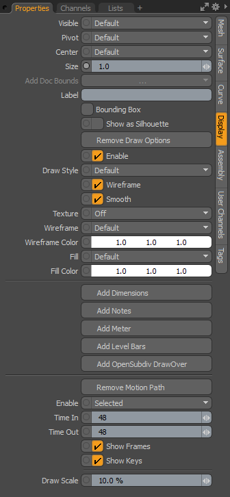
• Visible - sets visibility for the item itself in the 3D viewport: Default respects viewport settings, Yes sets the item as visible always, No disables visibility entirely.
• Pivot - sets visibility for the 3D item pivot: Default respects viewport settings, Yes sets the pivot as always visible, No disables pivot visibility entirely.
• Center - sets visibility for the 3D item center: Default respects viewport settings, Yes sets the center as always visible, No disables center visibility entirely.
• Size - a multiplier that adjusts the display size of the item's representations of camera, light, and locator icons. This does not affect the representations of mesh layers.
• Label - typing in text for the Label displays the text, positioned next to the 3D item, in the viewport for easy identification. It also adds two additional properties to control the display of the label in the viewport: Show Label and Label Offset.
• Show Label - temporarily enables/disables the display of the label in the viewport without losing settings; this is only available when a label is specified.
• Label Offset - specifies the distance away from the locator where the label appears; this is only available when a label is specified.
• Bounding Box - when enabled, Mesh Items display as a simple wireframe box around the geometry's total volume, instead of displaying the geometry itself.
• Show as Silhouette - when enabled, items draw only as a solid shape with no interior details. For the purposes of animation, it can be beneficial to view certain elements as a silhouette to ensure that key poses are expressing certain information. This works in conjunction with the Enable Silhouette setting of the 3D (OpenGL) Viewport display options, which must be enabled (the default state) for the silhouette to be visible.
Tip: The Show as Silhouette display option is only applicable to the Advanced OpenGL viewport display mode.
• Add/Remove Draw Options - opens/removes additional properties for adjusting how items display in the 3D Viewports. When selected, additional properties appear.
• Add/Remove Dimensions - when this option is enabled (by default), dimension values for the overall bounding box size appear in the viewport around the Mesh Item. An additional sub-tab shows in the Properties viewport, allowing further display customizations.
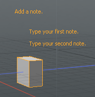
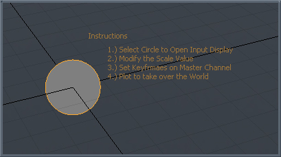
• Add/Remove Notes - when this option is enabled, you can define multiple lines of text (up to 9) that show up when the item is selected. An additional Multi-Line Note sub-tab shows in the Properties viewport, allowing further display customizations.
To add a note:
| 1. | In the Items list, select the mesh item you want to add a note to. |
| 2. | In the Properties list, on the bottom right panel, open the Display tab and click Add Notes. |
| 3. | Open the Multi-Line Note tab. |
| 4. | Set the options and type the text you want displayed in the viewport. |
• Add/Remove Meter - when this option is enabled, you can display an on-screen analog-style meter graph (looks like a speedometer) that can be rigged to show individual values in the 3D viewport. An additional sub-tab shows in the Properties viewport, allowing further display customizations.
• Add/Remove Level Bars - when this option is enabled, you can display an on-screen equalizer-type graph for visualizing multiple on-screen values. An additional sub-tab shows in the Properties viewport, allowing further display customizations.
Note: For more details on display customization, see Additional Draw Options.
• Add OpenSubdiv DrawOver - Enables the OSD drawing override, which draws Pixar subdivision surface using OpenSubdiv 3.0 instead of native Catmull-Clark and Subdivision polygon mesh drawing. This improves the drawing speed for high subdivision levels. When this package is added to mesh, instanced mesh or group item, The OSD draw package displays the subdivision surfaces instead of the standard drawing. The supported drawing styles are:
• Shaded (in all solid styles)
• Wireframe (wireframe style)
• Wireframe Overlay (wireframe on shaded model)
Note: The OSD drawing override doesn't support texture mapping and the adaptive subdivision of OSD.
In case of meshes consisting of mixed polygon types, other types of polygons, such as faces or curves, are not drawn.
• Enable - toggle the display of the Draw Options without losing values.
• Draw Style - allows you to choose a specific draw style for an individual Mesh Item; Default respects viewport settings.
• Wireframe - disabling the Wireframe checkbox disables the wireframe overlay on 3D Mesh Items.
• Smooth - disabling the Smooth checkbox disables the smoothing applied to polygon surfaces, making polygons appear faceted.
• Texture - controls the display of texture layers on a Mesh Item. Off disables texture display and Texture draws the texture without shading (this can make it easier to see a texture for painting), and Shaded Texture takes into account the shading of the surface to which the texture is applied.
• Wireframe - adjusts the draw color of the wireframe overlay of the 3D item in the 3D viewport.
• Wireframe Color - when Wireframe is set to Custom, the Wireframe Color sets the color of the wireframe.
• Fill - if Draw Style is set to Solid, this value controls the color of the 3D item's fill.
• Fill Color - when Fill Color is set to Custom, this value specifies the RGB color of the fill of the Solid in the 3D viewport.
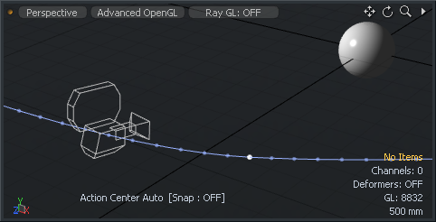
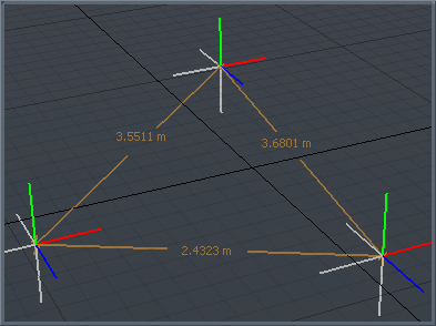
• Add/Remove Motion Path - to display the motion path for specific items within a scene (shown above for the Camera item for illustrative purposes), you can select the Add Motion Path option, revealing additional properties and controlling the display of the path in the 3D GL viewport.
• Enable - provides you with a means to toggle the display of the path On or Off, or to have the path only visible when the item is Selected.
• Time In/Out - the Time In option determines the number of frames before the current time in the Timeline that are displayed by the curve; Time Out determines the number of frames after the current time that are displayed.
• Show Frames - when enabled, displays the position of the element at each frame as a small dot along the path. This can be useful to see how the element moves in time, but can also get busy for some types of motion and can therefore be disabled.
• Show Keys - when enabled, displays the position of the element at each keyframe as a white dot along the path.
• Draw Scale - determines the size of the resulting motion path in the 3D viewport.
Assembly Tab
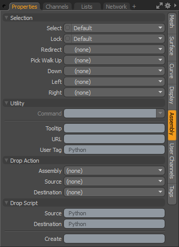
The following Selection options are available for the Mesh Item:
• Select - controls whether or not items are selectable within any 3D viewport: Yes enables direct item selection, No disables it. Items designated No can still be selected via the Items (Scenes) List.
• Lock - when enabled, items are locked from the application of any type of item transform.
• Redirect - when an item is selected in a 3D viewport, specifying an item for Redirect triggers Modo to automatically select the alternate item instead. This is helpful in easing item selections in complex hierarchies. Locators with special Display Viewport properties can be used visualize selectable items in the viewport that redirect to the actual item you wish to modify.
• Pick Walk - the arrow keypad can be used as a way to walk selections through a hierarchy. By default, parent items are selected by pressing up, and child items are selected by pressing down. The Pick Walk function allows you to specify which items, specifically, are selected by any of the four keys: Up, Down, Left, and Right. For instance, when you reach the bottom of a hierarchy, the foot, you could specify (by pressing the left or right arrows) the opposing foot would be selected, and by hitting down the head would be selected, and so forth.
The following Utility options are available for the Mesh Item:
• Command - specifies a command to fire when the item is clicked on in the 3D view. This can be any of Modo's commands. There are two commands that are especially useful when setting up assemblies:
• item.channelHaul - this selects any user channels on the item and activate the Channel Haul tool.
• item.channelPopover - this displays a pop-over form, containing controls for any user channels on the item. If used in conjunction with selection directions, this can also be used to display the channels belonging to a specific group.
Tip: The Command function is disabled on Mesh Items. To enable the option, you can convert a mesh to a Static Mesh by right-clicking on the item's layer name in the Item List and selecting the Change Type > Static Mesh option from the contextual menu. Note that converting a mesh to a static mesh is a destructive action, so make sure you have a backup copy should further editing be necessary to the Mesh Item.
• Tooltip - small blocks of text that appear, if assigned, when the pointer momentarily stays over an item. These can be notes or reminders to what an item is intended to do in a scene but tooltips can also be useful for an assembly author to provide some contextual instructions on how to work with an item in an assembly.
• URL - if a custom URL is assigned to an item, using the F1 help feature and clicking the item in the 3D viewport opens that particular location. This is useful for you to add custom documentation to an item.
• User Tag - a text string that can be used to identify particular items within an assembly or scene. These tags can be read by scripts with the item.userTag command. An example of use might be to identify items to be deleted or hidden when an assembly script has finished.
The following Drop Action options are available for the Mesh Item:
Assemblies offer you the ability to create a rig using Modo's many animation modifiers and then save the setup as a preset for easy application elsewhere.
Tip: You can drag and drop items over each other directly in the 3D viewport, pausing over an item automatically opens the drop action popup to customize the drop action.
In the following descriptions, the item being dragged is referred to as the source item and the item that has received the drop is referred to as the Destination item.
• Assembly - you can choose from a series of actions that are performed when the preset is initially dropped into the scene from the Preset Browser. The possible actions are as follows:
• Parent - the source item is made a child of the destination item.
• Parent in Place - the source item is parented as above, but with Compensation applied.
• Match - the source item is modified to match position, scale, and rotation of destination.
• Match Position - the source item is modified to match the position only of the destination item.
• Match Rotation - the dropped item is modified to match the rotation only of the destination item.
• Match Scale - the dropped item is modified to match the scale only of the destination item.
• Insert - inserts the source item into the hierarchy of the destination item. The item is positioned and orientated to match the destination item and becomes the parent of the destination item.
• Insert at Parent - similar to Insert but the source item matches its position and orientation to the destination item's parent (if a parent item is present).
• Insert in Place - the source item is inserted into the destination item's hierarchy as its parent but retain its current position and orientation.
• Place - positions the selected item at the intersection of the mouse pointer and the surface.
• Place and Align - positions the selected item at the intersection of the mouse pointer and surface, rotating the item to match the surface's normal direction.
• Source - the source Drop Action is performed when the assembly item is dropped onto a scene item. The same action options are available as for Assembly.
• Destination - as above, but the action is performed when a scene item is dropped onto the assembly item. The same action options are available as for Assembly.
Additional to the above actions, scripts can be assigned to run when certain actions occur:
• Source - the assigned script (omitting the @) run when this item is dropped onto another in the scene. The script gets the source item and destination item passed as arguments. If multiple items are dropped, then the script is called for each item in turn.
• Destination - same as above but the script runs when any item in the scene is dropped onto the item it's assigned to. As with the source Drop Script the source and destination items are passed to the script as arguments.
User Channels Tab
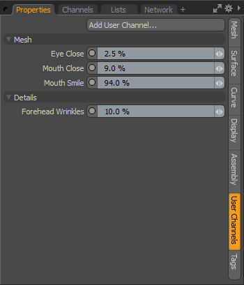
• Add User Channel - user channels are useful in rigging to make simplified controls for complex actions, or to simply give a name to a specific operation. The Add User Channel option allows you to add an unlimited number of user-defined Channels to an item. Once a user chanel is defined, it's necessary to connect the channel using the Schematic viewport, in order to make it operable. Pressing the Add User Channel button opens the Create User Channel dialog, where the actual channel is defined. This panel is fully covered in the Add User Channels topic.
As an example in the panel above, a number of user channels have been added and named by morph maps that are linked to the channels, allowing direct animation access. Other user channels are added that create dividers between the groups. Finally, another channel was also added and linked to an images opacity channel to control the amount of displacement. All of the defined user channels are then added to a channel group so they can remain on the screen for ease of animation.
Tags Tab
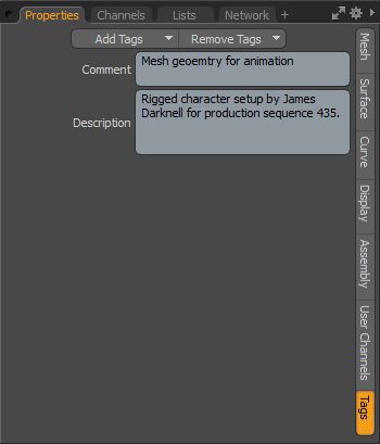
The Tag panel allows you to define various tags that remain associated to the specific item. These are typically text strings and are useful to add notes to specific elements for other users in a studio, or as reminders as to how something was meant to be used. There are a few pre-defined tags you can choose from or you can create your own specific tag definition.
Adding tags is done by pressing the Add Tags button, opening the pop-up menu and then selecting a tag type from the Add Tags menu. There are also options to Add Custom Tags, and Edit Tag definition, opening the appropriate panel in the Modo preferences.
Additional Draw Options
For all item types there are additional GL drawing properties that allow you to customize the UI for rigging in a number of ways, covered below in more detail. Options are toggled on/off with associated buttons in the Display sub-tab when the target item is selected. The action creates an additional sub-tab that appeares alongside the others in the Properties panel.
|
|
|
• Show/Hide Dimensions - when this option is enabled, an additional sub-tab appears in the Properties panel titled Dimensions. By default, dimension lines and values for the overall bounding box size appear in the viewport around a Mesh Item. The attributes in the Properties panel allow you to further customize the information that is displayed. Linking a series of items together through a hierarchy allows the display of distances between each object's Center point, from parent to child (and only when the parent item is selected the dimension values display).
Dimensions Tab
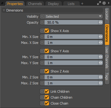
• Visibility - determines the visibility of the dimension lines to Off (not visible), On (visible), and Selected (only visible when selected).
• Opacity - controls the transparency of the dimension lines and numerical values displayed in the 3D viewport.
• Show X/Y/Z Axis - with these channels you can individually control the display for each axis.
• Min X/Y/Z Size/Max X/Y/Z Size - the minimum and maximum values can be assigned for each axis and, when the defined values for either Min or Max are reached, the dimension text displays in red in the viewport.
• Link Children - when set to true (the default option), draw the link lines to the child items. This is used to disable if the dimension line linking behavior is undesirable.
• Chain Child - when set to true, draw dimension lines from child to child in hierarchical order instead of from parent to each individual child.
• Close Chain - when set to true, draw an additional dimension line link back to the parent item from the last child item.
• Show/Hide Notes - when this option is enabled, an additional sub-tab appears in the Properties panel titled Multi-Line Note. This option allows for on-screen display of custom text strings, for information such as instructions. The text is useful to Riggers and TDs, or just to add some helpful reminders for an item when selected.
Note: Display text can also be positioned with the Label Offset control.
Multi-Line Note Tab
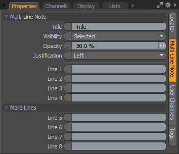
• Title - the first line of text that display above the Line entries.
• Visibility - determines the visibility of the dimension lines to Off (not visible), On (visible), and Selected (only visible when selected).
• Opacity - controls the opacity of the dimension line and numerical value displays in the 3D viewport.
• Justification - determines the justification of the text block to Left, Center, or Right.
• Line 1-8 - the text line entries that display in the 3D viewport.
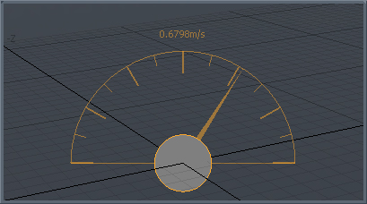
• Show/Hide Meter - when this option is enabled, you can display an on-screen analog-style gauge graph (looks like a speedometer) that can be rigged to show an individual value in the 3D viewport. An additional sub-tab appears in the Properties panel, titled Dial Meter, which allows some customization of the display.
Dial Meter Tab
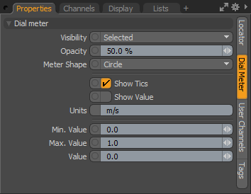
• Visibility - determines the visibility of the meter display to Off (not visible), On (visible), and Selected (only visible when selected).
• Opacity - controls the opacity of the meter readout and numerical value displays in the 3D viewport.
• Meter Shape - choose between a full Circle meter display and a Half Circle display.
• Show Tics - toggles the visibility of 15° and 30° interval lines in the display.
• Show Value - toggles the visibility of the Value information readout above the dial.
• Units - a text display that is positioned next to the Value display when the Show Value option is set to true.
• Min/Max Value - the minimum and maximum values determine the lowest value and the highest value that is displayed in the on-screen meter, controlling the overall position of the Value needle.
• Value - this is the input channel that determines the actual value displayed in the viewport, as well as the position of the meter needle (relative to the Min and Max values). Additional rigging is required in the Schematic viewport in order to connect the Value channel input from an output.
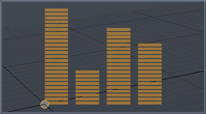
• Show/Hide Level Bars - when this option is enabled, an additional sub-tab appears in the Properties panel titled Equalizer Bars. This option is used to display an on-screen equalizer-style bar graph for visualizing multiple on-screen values relative to one another. Additional channels show in the Channels viewport, when enabled.
Equalizer Bars Tab
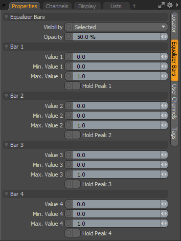
• Visibility - determines the visibility of the Level Bars to Off (not visible), On (visible), and Selected (only visible when selected).
• Opacity - controls the opacity of the level bars readout display in the 3D viewport.
• Value 1-4 - these are the input channels that determine the actual values displayed in the viewport, as well as the scale of the individual level bars (relative to the Min and Max values). Additional rigging is required in the Schematic viewport in order to connect the Value channel input from an output.
• Min Value 1-4/Max Value 1-4 - the minimum and maximum values determines the lowest value and the highest value, per readout, that is displayed in the on-screen level bar, controlling the overall scale of the bar displayed.
• Hold Peak 1-4 - like an audio readout, when the Max value is reached for any value readout, an indicator is drawn in the viewport. Toggle the Hold Peak value to reset the display.
Note: Up to eight bars total can be displayed by referencing the additional channels available in the Channels viewport.
Particle ID Channel
Individual items have a Particle ID channel that you can use to control the particle ID assigned to rendered surfaces. You can set this value manually, or drive it by a rig and then feed it to Shaders.
The Particle ID channel allows you to assign a value between 0.0 and 1.0 to a mesh item. You can specify it in the Channels list of the mesh item:
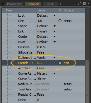
This channel is useful when using the Gradient or the Texture Switch node. Gradient values range from 0 to 100%, so a Particle ID of 0.5 corresponds to 50%, which results in a mesh with the color in the middle of a Gradient.
For Texture Switch, values are based on the order of connection. So if you have three textures, the first one is 0.0, the second connected texture is 0.5, and the third one is 1.0.