Lace Item
The Lace Item is a collection of commands designed to streamline the process of building laces in Modo.
Generating Laces
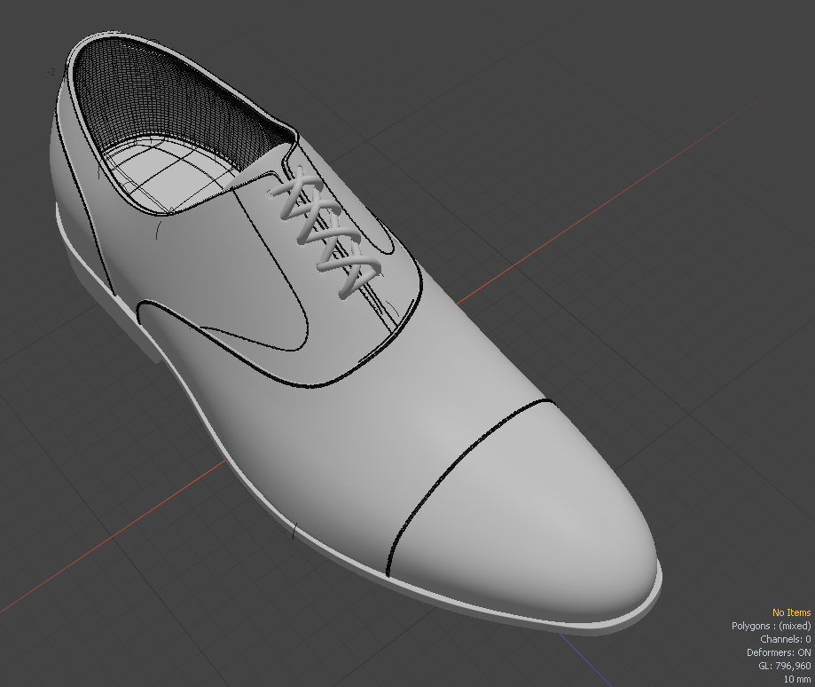
Before adding a Lace Item, make sure you have a scene containing the geometry you want to add the laces to, including the geometry for the holes the lace goes through. You can also have a lace shape ready in a separate mesh layer. This should be a flat polygonal geometry or a curve.
Accessing the Tool
In the Item List, click Add Item, then under Items > Procedural, double-click Lace Item.
A Lace Item is added to your scene and its properties appear on the lower right panel.
Specifying the Eyelets
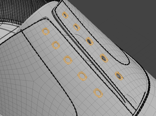
Next, you need to select the components to be used as the eyelets.
| 1. | In the 3D viewport, select the required polygons or edges. Each contiguous selection is treated as a point on the lacing path, so this works best by selecting edge or polygon loops around the holes a lace will pass through. |
Tip: It may be helpful to create a selection set and gradually add all the elements you need. This way, you avoid accidentally losing your selection, and it's easy to quickly select the required elements later. For more information, see Using Selection Sets.
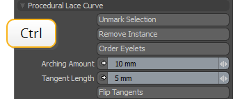
Tip: Hold Ctrl and click to unmark a selection.
| 2. | In the Lace Item's Properties panel, click Mark Eyelets. |
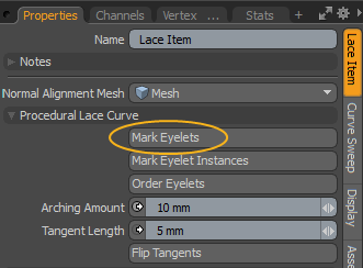
When your eyelet geometry is made up of instances, you can select them in the Item List, then click Mark Eyelet Instances. If you want to select all instances, hold down the Shift key. This changes Mark Eyelet Instances to Mark All Instances. Clicking the button marks all instances in your scene as eyelets.
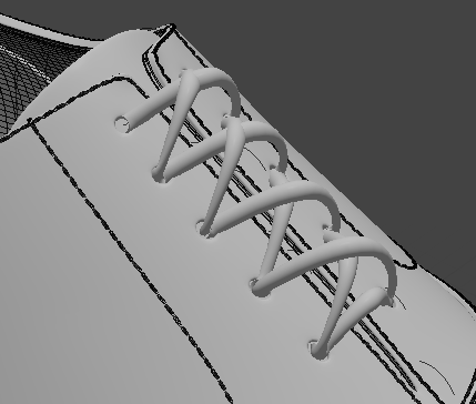
The selected geometry is now marked as eyelets for the lace. A Lacing Curve is generated and drawn in the 3D viewport.
Unmarking Eyelets
To remove your eyelet selection, hold down the Ctrl key. This modifies the behavior of the buttons and the following controls appear:
• Unmark Selection - Click to remove the eyelet selection.
• Remove Instance - Click to unmark the instances selected in the Item List.
Note: If you have selected all instances by Shift+clicking Mark All Instances, you can't remove them using Remove Instance.
Ordering Eyelets and Fine-tuning the Curve Path
The resulting curve generally doesn't follow the required path, so you need to re-order the points and adjust the tool properties.
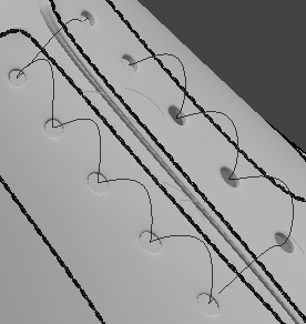
| 1. | Click Order Eyelets, and click on the blue points in the order you want the lace to go through them. |
The points are numbered in the viewport and the Lace Curve follows the new order. Click the thumbnail to see how eyelets are re-ordered.
| 2. | Adjust the other options as needed: |
|
Arching Amount |
Specifies how much the laces arch up above the surface. |
|
Tangent Length |
Each eyelet is a Bezier control point, and this option defines how tightly the curve goes into and out of the point. |
|
Flip Tangents |
Flips the Bezier tangents at a specific control point. This allows you to control how the curve bends around the control point. Clicking the Flip Tangents button selects the control points in the scene. You can then flip the tangents at a particular control point by clicking on it. |
|
Lace Curve |
Allows you to select an existing curve mesh along which to extrude the lace geometry. |
|
Freeze/Edit Lacing Curve |
The lacing curve built following the steps outlined here is fully procedural, and updates as the mesh geometry is edited or eyelet selections are updated. This is intended to serve as a good baseline for lacing, but any complex surface will likely require manual manipulation of the lace curve. This command converts the lacing curve to a standard editable mesh that can be manipulated. |
|
Lace Geometry |
The mesh the lace geometry is built to. When set to (none), Modo creates a mesh under the Lace Item. Here you can specify a different mesh layer. |
Building the Laces
| 1. | Click Build Lace Geometry to generate the laces. |
A dialog prompts you to set the shape for the lace geometry.
| 2. | Click the Shape Profile Type dropdown to select the shape type. The default setting is Existing Mesh. Select this to use geometry in an existing mesh layer. |
The other available options are:
• Profile Preset - Uses one of the Profile presets to generate the laces.
• Polygon Strips - Uses polygon strips to generate the laces.
• New Curve Mesh - Adds a new mesh containing a curve you can edit.
Note: You can modify these options later in the Curve Sweep properties. For more information, see Curve Sweep Properties.
| 3. | If you set Curve Source to Existing Mesh, click the Shape Source dropdown to select the mesh layer where the shape can be found. |
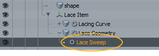
This generates the lace geometry using a Curve Sweep mesh operation. You can see it in the Item List parented under the Lace Item, called Lace Sweep.
The Curve Sweep properties are displayed on the lower-right panel. Edit them to further customize the lace geometry.
Note: For more information on the Curve Sweep mesh operation, see Curve Sweep.