Linear Align
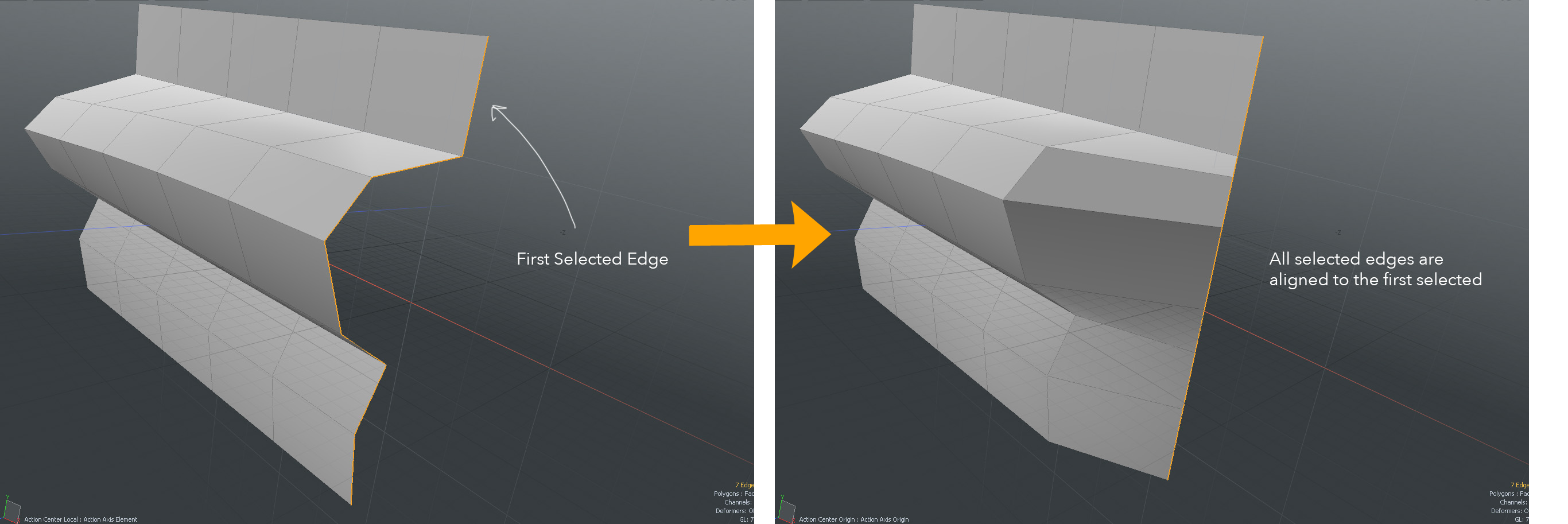
The Linear Align tool aligns selected vertices, edges, polygons, or UV positions along a line. Modo finds the outer-most vertices from selected edges or groups of edges and then interpolates other points between the end vertices. In Edges selection mode, the tool connects the selected edges and then aligns the connecting edge groups.
You can align multiple edge groups at once, but edge groups cannot intersect or cross over each other. In Vertices mode, Modo tries to connect selected vertices along edges. If the selected vertices are not continuous, Modo uses the vertex selection order. In Polygons mode, Modo uses the boundary edges and connects them as it does in Edges mode. The tool always aligns middle positions between corners of the overall boundary edges.
Courtesy William Vaughan
Activating the Linear Align Tool
Direct Modeling
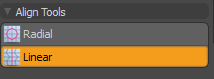
• In the Model layout, open the Deform tab on the left panel, expand Align Tools, and click Linear.
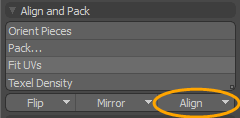
• In the UV layout, on the left panel, under Align and Pack, click the down arrow for Align options and click Linear.
Applying Linear Align
In this example, add a cylinder to your scene, create a selection of misaligned edges, and then apply the Linear Align tool. By enabling the Screen Align option, the Linear Align tool straightens selected edges in a line and keeps the depth position. Once done, click in the 3D viewport to apply the tool.
| 1. | In the Model layout, open the Basic tab in the left panel, and Ctrl/Cmd + click Cylinder. |
The cylinder primitive is placed at the center origin of your scene.
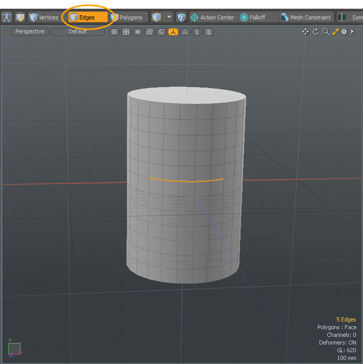
| 2. | Under the layout menu bar, click Edges to active the edges selection mode. |
| 3. | Press Shift + click on a number of consecutive edges. |
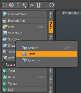
| 4. | On the left panel, open the Deform tab, and click Jitter. |
Tip: You can find the Jitter tool in the Deform sub-tab of the modeling toolbox (sometimes as a sub-option of the Smooth or Quantize tools).
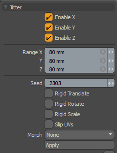
| 5. | Set the Range for X, Y, and Z to 80 mm, the Seed value to 2303, and click Apply. |
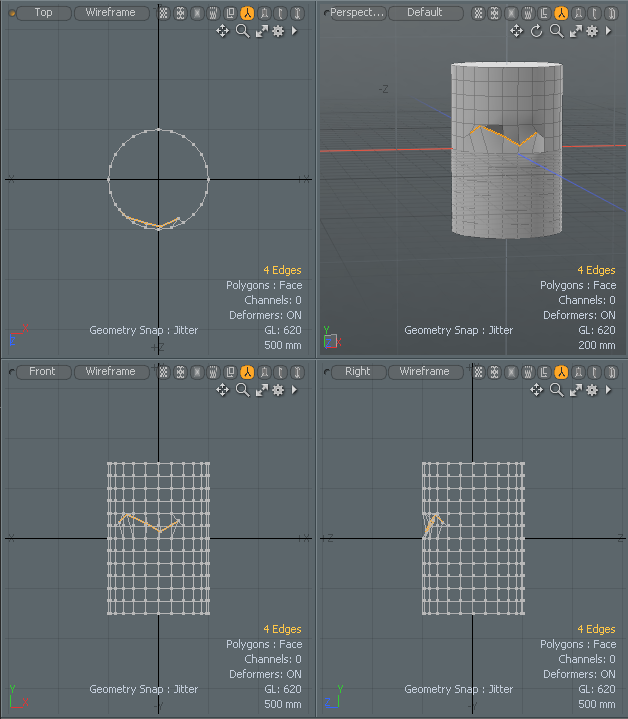
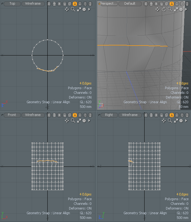
| 6. | In the 3D viewport, click the Minimize/Maximize arrow to view the mesh item in all four views (Top/Bottom, Perspective, Front/Back, and Right/Left views). |

The selected edges are misaligned edges.
| 7. | On the Deform tab on the left panel, expand Align Tools, and click Linear. |
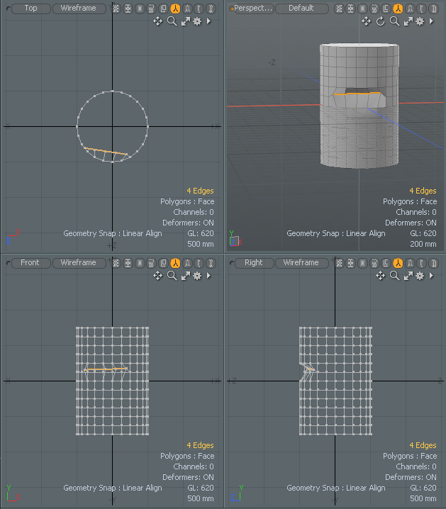
| 8. | Click anywhere in the Perspective view or another view to apply the default settings. |
The misaligned edges are now aligned to the first selected edge.
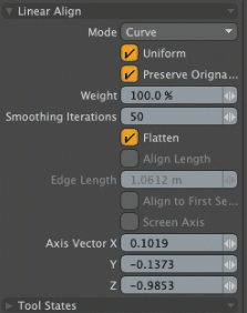
| 9. | In the Linear properties on the left panel, enable Screen Axis. |
The Linear Align tool straightens selected edges on screen view and keeps the depth position along screen space.
| 10. | Change any of the other Linear Align Properties to tweak your results. |
Linear Align Properties
|
Mode |
Determines how the target selections are aligned. • Line - interpolates linearly between the end positions.
• Curve - tries to fit a curve to the selected edges. |
|
Uniform |
When enabled, aligns points with the same spans; when disabled, Modo aligns the positions to the closest position along the line. |
| Preserve Original Curve | In Curve mode, this option fits the aligned curve points to the original curve shape as closely as possible. |
|
Weight |
Determines how to interpolate positions between the source (non-aligned) positions and the aligned positions. You can adjust this value interactively by dragging directly in the viewport. Additionally, the value for each position can be modulated by a falloff. |
|
Smoothing Iterations |
Specifies how many times Modo applies the smoothing operation. The Linear Align tool relaxes points inside of boundary edges only with selected polygons (in Polygons selection mode). |
|
Flatten |
Moves inner points to the circle plane before applying the smoothing process. This works only with selected closed polygons (in Polygons selection mode). |
|
Align Length |
Scales the edges or continuous selected open edges to the given length. This only works with selected open edges in Edges selection mode. The center of the scale is the averaged position from selected edges. The Linear Align tool uses the last selected edge as the initial length to re-size all others. |
|
Edge Length |
Determines the actual length of the resulting aligned segments when Align Length is enabled. |
|
Align to First Selected |
Aligns to the first selected vertex, edge, or polygon. The depth position of the selected edges along screen space is maintained. Note: When Screen Align is enabled this option is disabled automatically. |
|
Screen Align |
Straightens selected vertices, edges, or polygons on the screen view and keeps the depth position along screen space. The screen axis vector is stored in Axis Vector X, Y, and Z, which is set by clicking in the 3D viewport. |
|
Specifies the X, Y, and Z axis values to align the selected vertices, edges, or polygons. |