Bridge
The Bridge tool creates polygons to span the area between selected edges or polygons. The Bridge tool has several options to control how Modo generates the spanning polygons to connect the two locations.
The Bridge tool is found in the Model layout Toolbox, under the Duplicate, Edge, and Polygon sub-tabs. It is also found in the Topology layout Tools sub-tab. In addition, you can also activate it by choosing Geometry > Duplicate > Bridge.
Prior to activating the tool, you must select at least two polygons that do not share any edges. The first polygon (or cluster of polygons) selected connects with the second polygon (or cluster of polygons). Make sure each cluster (or individual polygon) does not share any edges with the first selection for Modo to determine how to bridge from one location to the next.
Note: You can use Edge selections as well — as long as they don't share any vertices between the two or more selections.
Once you specify the selection, clicking the Bridge tool icon activates the tool. Clicking again in the 3D viewport enables the interactive mode for you to drag and interactively adjust the number of segments between the polygon clusters.
Bridge Tool Properties
You can adjust additional options in the tool's Properties panel.
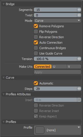
Bridge Properties
Segments: Determines the number of polygons that Modo creates across the length of the bridge. You can set this value interactively by dragging in the 3D viewport while the tool is active or numerically in the Properties panel. For curved bridge spans or those modulated by a profile, having more segments produces smoother results.
Twist: Rotates the bridge polygons between the original connection points when set to a non-zero number. This is useful to clean up bridges between disparate polygon selections where the bridge can become overlapped. By specifying the Twist value you may be able to untangle the bridge manually.
Mode: Sets the interpolation style of the generated bridge polygons.
Linear- Creates a bridge in a straight line between the original selection.
Curve- Creates an arc between the original selection points. You can further refine the curve by adjusting the Tension setting.
Smooth- Creates an "ease in/ease out" blend between the original selection sections.
Remove Polygons: When enabled, removes the originally selected polygons used to create the bridge if you selected polygons prior to activating the tool. This is enabled by default and is the preferred behavior.
Flip Polygons: When enabled, flips the normals of the newly created polygons in the bridge. Use when a negative bridge action causes the resulting polygons to appear inside-out.
Reverse Direction: When enabled, reverses the normal direction of the target polygon cluster when bridging. This can help resolve a skewed bridge span that can't be resolved by adjusting the Twist value alone.
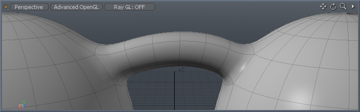
Auto Connection: When enabled, adds segments automatically, connects them to adjoining boundary edges when bridging opposing edges within the same surface, and attempts to retain the surrounding curvature.
The video shows the edge selection prior to activating the tool, then the tool activated on the selection bridging between the two clusters, and finally with Auto Connection enabled, Modo adds additional spans automatically and connects them to the border edges.
Continuous Bridge: When enabled, bridges successive clusters of polygons or edges into a continuous length or tube with the spans evenly divided between each individual span. Selection order determines the order in which Modo bridges the spans.
Use Guide Curve: When enabled, uses a guide curve to determine a single continuous edge along the final bridged span that may eliminate a twisting issue. When using the Bridge tool to connect consecutive curves created with the Contour tool, twisting may occur in the resulting geometry. You can select a single vertex from each curve and press Shift+O on the keyboard to create an open curve to serve as a guide curve. Then switch to Polygon selection mode and select all the curves in order, with the guide curve last. Do this before activating the Bridge Tool and enabling Use Guide Curve.
Tension: Provides additional control over the bridge path used when Curve mode is active. Increasing this percentage value accentuates the curved effect and decreasing it mutes the effect toward the linear path.
Make UVs: Determines how Modo generates a UV map automatically for the resulting geometry.
Connected- Connects the edges between existing UV values as a straight line.
U/V- Fills the entire UV map 1-0 area with the resulting bridged geometry in the specified orientation.
Curve Properties
It is possible to bridge between selections of two curves or, by enabling Continuous Bridge, a series of successive curves. You can control the smoothness of the bridging in these cases by adjusting the Segments between spans and the Steps across the curve. The Tension setting controls how smoothly one span blends into the next.
Automatic: When enabled, determines automatically the Steps value by subdividing the curve based on the Mesh Item layer's Curve Refinement Angle setting.
Steps: Determines the the number of curve subdivisions when Automatic is disabled. Larger values produce smoother surfaces; smaller values produce more faceted surfaces.
Profile Attributes Properties
Inset: Specifies the X direction offset amount of 1D profile.
Reverse Direction: When enabled, evaluates the 1D profile from top to bottom.
Reverse Inset: When enabled, reverses the Inset value to mirror the profile.
Keep Aspect: Sets the Inset value automatically based on the aspect ratio of the profile.
Profiles: Provides a list (essentially a mini Preset Browser) for viewing various profiles. This works the same as the standard Preset Browser.
Join Meshes Procedurally Using the Bridge MeshOp
The bridge MeshOp allows you to quickly bridge between two or more faces or edges on a single mesh and join them. Unlike the direct modeling bridge tool, the Bridge MeshOp also allows you to adjust parameters such as segments, twist, and tension even after the tool is applied and can continuously be adjusted at any stage of your modeling process without needing to rebuild geometry or reapply the operation.
Activate the Bridge MeshOp by choosing Mesh Operations > Edit> Bridge in the Mesh Operations viewport, or by going to Add > Mesh Operations > Edit > Bridge in the Schematic viewport.
You need to select at least two polygons that do not share any edges or at least two edges that do not share any vertices to join meshes with the Bridge tool. The Bridge creates a polygon that spans from the first edge or face selected to the second face or edge selected.
To apply a Bridge MeshOp:
-
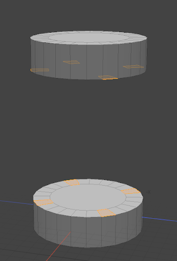
Select two or more faces or edges on your geometry. In this example, we will be selecting faces, but the workflow is the same for bridging edges.
-
In the Mesh Operations viewport, click the Add Operation button.
-
Add a Bridge operation.
-
Tip: The Bridge MeshOp can also be applied via the Schematic viewport by dragging your mesh from the Items List into the Schematic viewport, selecting the faces you want to be bridged and then clicking Add.
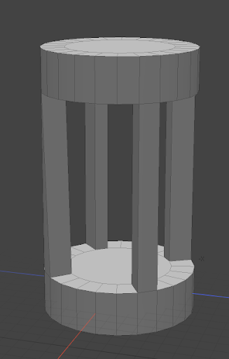
A bridge is applied between the mesh selections.
Bridge MeshOp Properties
|
Selection Type |
Specifies whether Polygons or Edges are being bridged. Modo sets this automatically depending on what is selected when the operation is applied, but you can change the type at any time. |
|
Segments |
Allows you to set the number of polygons that Modo creates across the length of the bridge. Increase or decrease the number of segments by dragging in the 3D viewport, or by entering a number in the Properties panel. For curved bridge spans, a higher number of segments produces smoother results. |
|
Twist |
Enter a number higher than zero to rotate the bridged polygons between the original connection points. |
|
Mode |
Sets the interpolation style of the bridge polygons generated: • Linear - Creates a bridge in a straight light between the original selections. • Curve - creates an arc between the original selections. The curve can be further refined by adjusting the Tension setting. • Smooth Creates an “ease in/ease out” blend between the original selections. |
|
Remove Polygons |
When enabled, removes the polygons originally selected to create the bridge. This is enabled by default and preferred behavior. |
|
Flip polygons |
When enabled, flips the normals of newly created polygons in the bridge. You can enable Flip Polygons when a negative bridge action causes the resulting polygons to appear inside-out. |
|
Reverse Direction |
When enabled, reverses the normal direction of the target polygon cluster. This can help resolve a skewed bridge span that can't be corrected by adjusting the Twist value alone. |
|
Auto Connection |
When enabled, segments are created automatically and connected to adjoining boundary edges when bridging opposite edges within the same surface. Auto connection also helps to retain the curvature of surrounding geometry. |
|
Continuous Bridge |
Bridges all selected polygons or edges into one continuous length or tube with spans divided between each span. The selection order determines the order in which Modo bridges the spans. Continuous Bridge is enabled by default, but should be disabled if multiple independent polygons or edges are being bridged at once. |
|
Close Bridges |
When this option and Continuous Bridge are enabled, the last selection is connected to the first selection. This is useful for making radial or sweeping bridged shapes. |
|
Use Guide Curve |
When enabled, Modo uses a guide curve to determine a single continuous edge along the final bridged span that may help to eliminate twisting. Tip: When using the Bridge tool to connect consecutive curves created with the Contour tool, twisting may occur in the resulting geometry. You can select a single vertex from each curve and press Shift+O on the keyboard to create an open curve to serve as a guide curve. Then switch to polygon selection mode and select all the curves in order, with the guide curve last. Do this before activating the Bridge Tool and enabling Use Guide Curve. |
|
Tension |
Provides additional control over the bridge path used when Mode is set to Curve. Increasing this percentage value accentuates the curved effect and decreasing it mutes the effect toward the linear path. |
|
Make UVs |
Determines how Modo generates a UV map automatically for the resulting geometry. |
|
Connected |
Connects the edges between existing UV values as a straight line. |
|
U/V |
Fills the entire UV map 1-0 area with the resulting bridged geometry in the specified orientation. |
Using Content Presets With the Bridge MeshOp
The Bridge MeshOp can also be used with content presets to change the shape and silhouette of your bridge. Because of the procedural nature of the Bridge MeshOp, some extra setup is required to use content presets than there would be with the direct modeling version of the Bridge tool. Content presets are added to the Bridge MeshOp from the Mesh Operations viewport or via the Schematic viewport.
To add content presets in the Mesh Operations viewport:
-
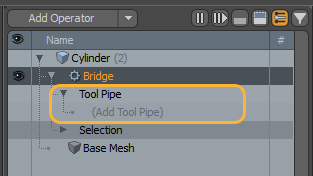
In the Mesh Ops list, expand the Bridge MeshOp so that the Tool Pipe parameter is exposed.
-
Click (Add Tool Pipe).
-
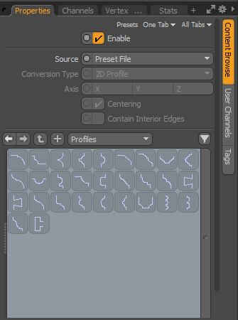
Add a Content Preset MeshOp by navigating to Tool Pipe > Sub Tools > Content Preset,
-
In the Properties panel, select a preset to use.
OR
By tying Content Preset in the search field.
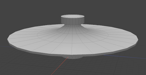
The selected preset is applied to the bridge.
To add presets in the Schematic Viewport:
-
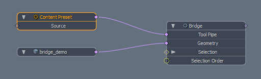
Drag the mesh item containing the Bridge MeshOp from the Item List into the Schematic viewport and double-click the diamond port on the node to expose connected nodes.
-
In the Schematic viewport, click Add and navigate to Mesh Operations >Tool Pipe > Sub-Tools > Content Preset or by type Content Preset in the search field.
-
Connect the Content Preset to the Tool Pipe port on the Bridge node.
-
In the Properties panel, select a preset to use.

The preset is applied. In both cases, once the preset is applied, you can continue to adjust the properties of the Bridge MeshOp such as Segment, Twist, and Tension within the Properties panel.