Using Utilities
Ruler Tool
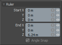
The Ruler command creates a virtual measuring device in the viewport that lets you quickly measure the distance between two locations. To activate the tool, in the menu bar, click View > Ruler Tool. Once activated, the Ruler becomes visible in the 3D viewport, adding an additional tool Properties panel. You can hover the mouse cursor directly over the handles at either end and click and drag to position the handles in the scene. The values on the ruler interactively update as the ruler is positioned in the scene. The value displays are view-dependent, so moving the view position of the viewport adjusts the values for ease of reading. At either end, there is a readout of the ruler's total length. To reposition the ruler itself, you can click and drag the ruler element, repositioning it within the scene. You can also use the Ruler Start and End fields of the property form to define a fixed size ruler within the scene. When combined with the Applying Snapping function, the ruler is a powerful option for measuring elements in a scene.
Protractor Tool
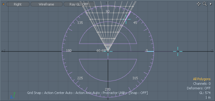
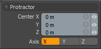
The Protractor tool provides you with a simple visual method for accurately measuring angles in the 3D viewport. You can activate the tool in the menu bar, in View > Protractor Tool. Once activated, the Protractor tool becomes visible in the 3D viewports. There are three handles you can use to position and measure elements in the scene. The handle at the center of the Protractor itself positions the tool within the scene. The second tool handle controls the rotation of the tool representation and the third handle measures the angle, producing the readout display. To adjust a handle, you can simply hover the mouse pointer over the handle representation and click and drag to adjust. You can also use the tool's Properties panel to position the center of the Protractor. When combined with the Snapping function, the Protractor is a powerful option for measuring angles in a scene.
Dimensions Tool
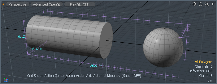
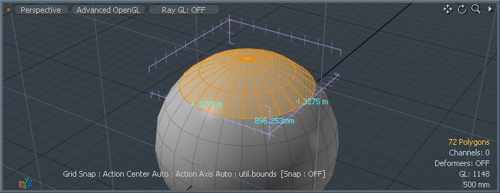
The Dimensions tool displays the bounding box dimensions of any object or component selection. When activated through the menu command View > Dimensions Tool, the dimensions become visible within the 3D viewport, displaying the size of the element in all three axes. The Dimensions tool requires no user input or interaction outside of making a selection.
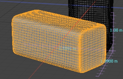
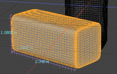
Enabling the Orient to Selection control displays the dimensions relative to the selected element, rather than aligned to the major axes. This makes the measurements easier to read in the context of your selection.
|
|
|
|
Orient to Selection disabled. |
Orient to Selection enabled. |
The Absolute Scaling and Uniform Scaling tools also include the Orient to Selection control, which causes the Grab Size button to account for the orientation of your selection and performs any uniform scaling relative to that orientation, rather than along the major axes.
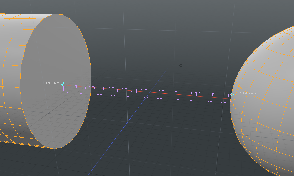
Measure Scene Distances with the Ruler Array
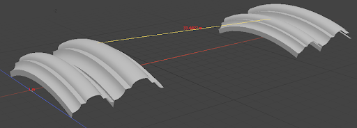
The ruler allows you to select vertices on two objects and then draw a polyline to calculate their distance. This is useful when working to a specific scale or scene layout where you may be working to a reference or blueprints. Guides created by this operation can also be used as guides for snapping. The ruler is available as a MeshOperation or as a direct modeling tool.
To use the ruler as a direct modeling tool:
-
Select two or more meshes in the item tree to make them active in the scene.
-
Switch to Vertices mode using the button above the viewport.
-
Select two or more vertices on separate, active meshes.
-
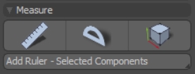
In the Create tab in the toolbar, click the Add Ruler button.
-
Right-click the Add Ruler button to apply different types of ruler from a dropdown list:
A ruler is created between the selected vertices.
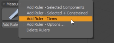
• Add Ruler - Selected Components: Applies a ruler between two or more selections, but the ruler does not update if any selected components are moved
• Add Ruler - Selected + Constrained: Adds a ruler between two or more selections and constrains the ruler to the selection origin. This means if you move any of your selected objects, the ruler updates to match any changes in distance.
• Add Ruler - Items: Allows you to create rulers between multiple items instead of selected points on an item. Like Selected + Constrained, a ruler created by the items option automatically updates the distance displayed if any items are moved.
• Add Ruler - Options…: Allows you to specify that you want a ruler created only between selected items and enables you to constrain the ruler. You can also specify the axis the ruler is locked to in the options window.
• Delete Ruler: deletes any ruler arrays present in the scene.
To use the ruler as a MeshOp:
-
Select two or more meshes in the item tree to make them active in the scene.
-
Switch to Vertices mode using the button above the viewport.
-
Select two or more vertices on separate, active meshes.
-
In the Mesh Operation viewport, add a Ruler MeshOp.
-
In the Ruler Properties tab, change the Input Method to Selected Vertices.
A ruler is created between the selected vertices.
Ruler MeshOp Properties
Using the Ruler MeshOp gives you greater control over your ruler and allows you to adjust how it looks with parameters such as Tick Offset, Tick Length, and Text Scale.
| Input Method |
• Local Values - Uses the A and B values at the bottom of the form. • Array - Uses the input array channel to get positions. • Selected Vertices - Creates rulers between selected vertices on the current mesh. If no vertices are selected, Modo attempts to connect all vertices. |
| Facing Axis |
Sets the axis to which the ticks and distance face. |
| Draw Ends |
When enabled, draw polylines to represent the end of the ruler. |
| Draw Ticks |
When enabled, draws ticks at even intervals between the start and end of the ruler. |
| Tick Offset |
When Draw Ticks is enabled, this control determines how far apart the ticks are placed. |
| Tick Length |
When Draw Ticks is enabled, this control determines the length of each tick. |
| Tick Vertices |
When Draw Ticks is disabled, this control determines if ticks are still drawn or not. |
| Draw Distance |
When enabled, draws a text polygon showing the distance between the selected vertices. |
| Font |
Sets the font used to display distances. |
| Text Offset |
Sets how far from the ruler the text is drawn. |
| Text Along Ruler |
When enabled, the text is drawn along the ruler. When disabled, the text is drawn horizontally. |
| Text Scale |
Sets the size of the display text. |
| Use Offset |
Allows a World Position Matrix to be plugged in, controlling where the ruler starts. |
| Link To Offset |
When enabled, draws polylines offset from the original selected positions. |
| Offset Draw Style |
When Link to Offset is enabled, controls how the offset lines are drawn. |
| Extend Distance |
Extends the ruler in all directions by this value. |
Drawing the Distance Between Arrays
The Measure Array Distance node, available in the Schematic viewport, also allows you to measure the distance between arrays.
To use the node, plug your chosen array into the Input Array channel in the Measure Array Distance node.
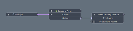
Once plugged in, you will be able to see the distances between arrays marked in the 3D viewport.
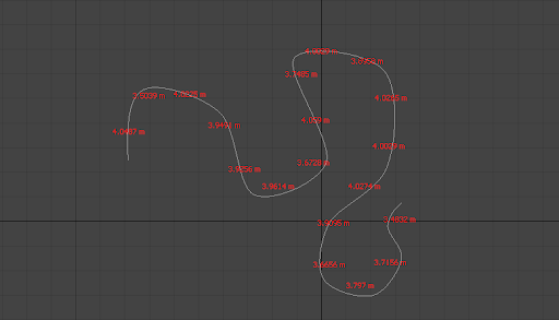
In the Properties tab of the Measure Array node, you have the option to offset the distances from their respective points and to draw a GL line between them.