Render Item: mPath Renderer Settings
The Render item's Settings tab allows you to adjust render settings specific to rendering quality.
The following Render item properties are available on the Settings tab for the mPath renderer.
Tip: See Rendering with mPath to learn more about the mPath rendering workflow and denoising.
| Option | Description |
|
Apply Preset |
Allows you to create and save custom render settings as presets to reuse in other scenes. You can set any of the property settings within the sub-tabs and click the Store Preset
• Store Preset • Remove Preset |
|
Renderer |
Choose between Modo's Default renderer and mPath. |

mPath Settings
Note: mPath automatically uses Environment Importance Sampling if an active texture layer such as an HDR image map is affecting the environment. See Environment Importance Sampling to learn more.
| Option | Description |
| Ray Tracing Engine |
When Renderer is set to mPath, this allows you to choose whether to use a CPU only, or a GPU ray tracing engine. The following options are available: Note: A warning icon • Foundry SSE (CPU) - Uses only the CPU for ray tracing. • Intel Embree (CPU) - Offers increased performance for CPU ray tracing, providing you have an Note: Deformation Motion Blur is currently unsupported with Intel Embree (CPU). An " • NVIDIA OptiX (GPU) - Offers increased performance, allowing for multiple buckets to take advantage of GPU raycasting simultaneously. Note: If you see an " Note: Modo is using the OptiX 7 ray tracing engine. Transform motion blur is supported by this engine, but deformation motion blur is not currently supported. Tip: The NVIDIA OptiX option works on non-RTX cards, however true RTX hardware shows increased performance over non-RTX. Be sure to download the latest NVidia drivers, version 435 or higher. • Metal (GPU) - Modo's Metal support provides GPU extension and shadow ray tracing to improve render performance on Apple hardware. You can still select this option if you don't have Apple hardware so that you can set the mPath Settings before rendering on a remote Mac. Note: Due to Modo’s minimum supported version of macOS Catalina (10.15) the Metal ray engine does not currently support: |
|
Shading Engine |
Select the shading engine to use along side the Ray Tracing Engine: Note: A warning icon • Base Material (CPU) - shade using a default base material. This mode is useful for quick, lower quality performance comparisons to see how materials behave. • Shading Tree (CPU) - the default option, shade using the primary CPU. • NVIDIA CUDA (GPU) - shading with improved quality and speed using NVIDIA CUDA on the primary GPU, if available. You can still select this option if you don't have an NVIDIA GPU on your local machine so that you can set the mPath Settings before rendering on a remote CUDA capable machine. |
|
Note: See Current Limitations in mPath for more information on the limitations of rendering with mPath. |
|
|
Maximum Quality |
Antialiasing primary quality control. Specifies the minimum and maximum number of samples per pixel. The renderer iterates through a series of passes. When Maximum Quality is set to a low value, you get a quick first iteration, providing a noisy preview of the scene. |
|
Antialiasing Filter |
Allows you to choose different antialiasing filters. The Antialiasing Filter determines the pattern to use when evaluating a pixel. The default is Gaussian, which performs very well in most cases, and offers a good balance of performance and quality. The other options are: • Box • Triangle Note: The Antialiasing Filter option may be hidden. Click the More button at the bottom of the panel to display all controls. |
|
Noise Threshold |
Specifies the degree of noise that's acceptable to determine when a pixel is skipped. If a pixel inside a render bucket achieves a satisfactory level of refinement, it is skipped for each additional iteration, speeding up the render. Higher values lead to faster but noisier renders. Tip: The default value of 5% is recommended, however 10-20% can be acceptable if denoising is applied afterwards. |
|
Diffuse Depth |
Specifies the maximum number of bounces for Diffuse rays before they are automatically terminated. Higher values increase render time but produce more accurate results. |
|
Reflection Depth |
Specifies the maximum number of bounces for Reflection rays before they are automatically terminated. Higher values increase render time but produce more accurate results. |
|
Refraction Depth |
Specifies the maximum number of bounces for Refraction rays before they are automatically terminated. Higher values increase render time but produce more accurate results. |
|
Path Threshold |
Eliminates rays that have little or no impact on the final rendered image. As rays are fired, they are assigned an importance value. This value can increase or decrease at each bounce, depending on the surface values contribution. If a ray's importance value falls below the Path Threshold, Modo decides whether to kill the ray or trace it further. Increasing this value can decrease render time at the cost of quality. Note: The Path Threshold option may be hidden. Click the More button at the bottom of the panel to display all controls. |
|
Maximum Radiance |
Controls the Maximum Radiance carried by secondary rays. This can be helpful in reducing noise and preventing fireflies (single bright pixels) caused by small but very bright features of a scene, such as tight specular highlights or surfaces very close to point light sources. It acts as a multiplier for the most highly-exposed render output in the scene. Setting the Maximum Radiance to 10.0 (the default value) means that a ray is ten times brighter than the brightest render output. It is recommended to keep this value above 1. Note: The Maximum Radiance option may be hidden. Click the More button at the bottom of the panel to display all controls. |
|
Indirect Caustics |
Indirect caustics are a natural rendering by-product of physically-based rendering. You have the following options to control their creation: • None - Disables all indirect caustics within a scene. • Reflection Only - Caustics are only calculated for reflective surfaces. • Refraction Only - Caustics are only calculated for refractive surfaces. • Both - Caustics are calculated for both reflective and refractive surfaces. Note: The Indirect Caustics option may be hidden. Click the More button at the bottom of the panel to display all controls. |
Geometry
The following Geometry options are available for the Render item:
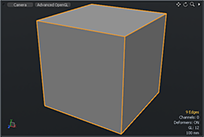
The first two settings under the Geometry section are global controllers that relate to Subdivision Surface (SDS) models in a scene. Subdivision Surfaces is a means of producing a smooth, continuous mesh at render time, based on a low resolution proxy model (sometimes called the "cage" or Limit Surface). Generally, when straight polygon modeling, surfaces are made from faces - each its own tiny flat plane that, when shaded together, simulates a smooth surface - but silhouette edges can reveal the faceted nature of the model. The traditional fix for this limitation is to simply add more polygons, but controlling all those real polygons can quickly become unwieldy. For a SDS model, the polygons in the low resolution model are automatically divided and refined recursively in such a way that the resulting model is a smooth organically curving surface.
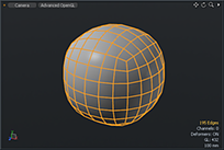
In Modo, you can toggle any object as an SDS model by simply pressing the Tab key. You can control the level (number of times the models is subdivided) using the Subdivision Level setting found in the Mesh Item properties viewport. Higher values produce smoother models, but generate more geometry that requires more processing time and memory to render. When the Adaptive Subdivision setting is enabled, this function overrides the Mesh Item setting at render time allowing you to adaptively control all the Subdivision Surfaces in a scene globally.
|
|
|
|
|
|
Original 'Cage' Geometry |
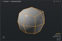
SubD level of 1 |
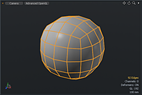
SubD level of 2 |
SubD level of 3 |
|
Option |
Description |
|---|---|
|
Adaptive Subdivision |
Toggles the Adaptive Subdivision function in Modo. When enabled, Modo adaptively tessellates all SDS meshes at render time. Which is to say, depending on the user settings, the mesh is refined repeatedly until all polygonal edges fall within the set subdivision rate. |
|
Subdivision Rate |
Enabling Adaptive Subdivision sets the subdivision rate for the level threshold for all SDS geometry in a scene. Defined as pixels, the default rate is 10, which means that Modo picks a subdivision level for that mesh, such that the length of edges for any group polygons in the largest subdivision patch appear no more than 10 pixels long (most are shorter than that). This is very useful since it means that subdivision levels automatically adapt to each mesh's distance from the camera, the zoom factor, and similar. If you really want to minimize your polygon count, you can set the subdivision rate to a huge number such as 1000. On the other hand, if you never want to see a faceted edge in a render you can reduce this number to 5 or less. Be warned that reducing the subdivision rate comes at the expense of additional system memory use and performance loss. |
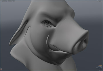
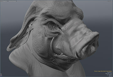
The next five settings control Modo's Micropolygon Displacement function: a means of adding fine geometric detail to surfaces by way of a texture-based controller. Similar in nature to Subdivision Surfaces, polygonal surfaces are automatically divided and refined recursively producing finer and finer micropolygons, which are then displaced (pushed in or out in the polygons normal direction) based on a grayscale value (and user settings in the Texture Locator item).
This can result in an incredible amount of detail for models that would be difficult or impossible to create otherwise. This is similar to a bump map, but where a bump map is a rendering trick that simulates detail on a surface and often looks imperfect, displacement is actual geometry. Displacement maps can be created in Modo, using any of the painting or sculpting tools, generated in an external application and applied to the object, or simply applied as a procedural texture layer in the Shader Tree. For best results, you should enable SDS for any surfaces with displacement applied. Please refer to the Effect - Texture Item topic for more information on working with displacement maps.
|
|
|
|
SDS Limit Surface |
Displacement Map applied |
|
Option |
Description |
|---|---|
|
Micropoly Displacement |
When an object's surface has displacement applied in the Shader Tree, this checkbox toggles the rendering of micropolygon displacement on a global level. |
|
Displacement Rate |
When Micropoly Displacement is enabled, the Displacement Rate, sets the threshold to which the geometry is subdivided into micropolygons. Similar to the Subdivision Rate, micropolygon displacement is adaptive, evaluating every polygon edge separately. The distance from the camera to the center of the edge (the focal length), and the render resolution are used to convert the Displacement Rate (in pixels) into a distance in world space. If the edge is longer than this and also longer than the Minimum Edge Length, it is split in half. This process continues recursively until all edges satisfy those requirements. |
|
Displacement Ratio |
Note: The Displacement Ratio option is hidden by default. Click the More button at the bottom of the panel to display all controls. When set to 1.0, objects are tessellated a consistent amount across their entire surface, but when displacing large areas, such as a ground plane in an environment, where a good deal of the geometry lays outside of the view of the camera, most of those polygons are going to waste, filling up your system's memory. The Displacement Ratio reduces the number of displaced polygons outside the camera's view. The higher the number, the greater the reduction in polygons. Keep in mind though that reflective and refractive objects still are able to see these areas outside the camera's view, so high settings may begin to introduce artifacts to your image. |
|
Minimum Edge Length |
Note: The Minimum Edge Length option is hidden by default. Click the More button at the bottom of the panel to display all controls. Each edge in the mesh is tessellated until polygons satisfy the Displacement Rate setting. Ungoverned, this can go out of control resulting in ridiculous numbers of polygons. The Minimum Edge Length sets a minimum length for any polygonal edge. Once an edge has reached that minimum length it can no longer be split. A simple and effective throttle for controlling the amount of polygons in your scene. |
|
Smooth Positions |
Note: The Smooth Positions checkbox is hidden by default. Click the More button at the bottom of the panel to display all controls. When a surface is diced into micropolygons, the initial positions of the micropolygon vertices lie on a curved surface based on the original smooth vertex normals. So, if you start with a regular non-SDS sphere, for example, it'll be diced into a smooth sphere, and then the displacement texture is applied to that. You could even use this as an alternative to subdivision surfaces by just applying a displacement texture that is zero everywhere (although the resulting surfaces are different from SDS in that they actually pass through the original vertices). The ability to turn off position smoothing, which means that all the initial positions of the micropolygon vertices lie exactly on the flat planes of the original polygons. Doing this in the non-subdiv sphere example would cause the diced version to look faceted. The reason this feature was added was that it's necessary to turn off position smoothing when using a displacement map created by object-to-object baking, since the distances in the map are measured based on the original polygons of the low-poly object and not the smoothed polygons. |
|
Displacement as Bump |
Note: The Displacement as Bump checkbox is hidden by default. Click the More button at the bottom of the panel to display all controls. When this option is enabled, Modo also applies any displacement maps as a bump map, providing a finer detail evaluation that requires lower number of subdivisions to achieve. This can be used to reduce the amount of memory necessary to render complex scenes when combined with lower subdivision rates. |
|
Indirect LOD |
Note: The Indirect LOD checkbox is hidden by default. Click the More button at the bottom of the panel to display all controls. When this option is enabled, Modo holds an additional lower resolution version of displaced geometry used strictly in calculating indirect lighting, reducing overhead in global illumination calculation. However, it may end up using slightly more memory as two distinct copies of the same geometry may be held in memory simultaneously. |
| Render Output Masking | Supports group masks and layer masks in the Shader Tree. |