Flip UV
The Flip UV command allows you to horizontally or vertically flip UV orientations for an entire map or a selected area of it. This is useful for quickly changing the position of the texture applied to the UV.
To access the tool:
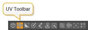
| 1. | Open the UV toolbar by clicking the UV tab at the top of the left panel: |
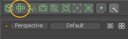
Alternatively, open the UV layout from the Switcher bar.
Note: You may need to disable the Starred Only ![]() button on the right to reveal the UV layout button.
button on the right to reveal the UV layout button.
| 2. | If working in the Modo layout, click the gray line above the 3D viewport to reveal additional controls, and click the UV viewport button. |
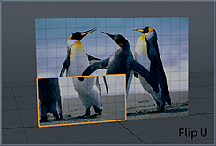
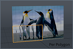
The Modo layout has separate buttons for Flip U and Flip V. To flip a selection per polygon, hold Alt when clicking either of these buttons.
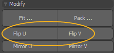
If you're working in the UV layout, click the Flip button and select the appropriate option.
• Flip U - flips the entire selected area on the horizontal axis, based on the selection's bounding box center location.
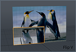
• Flip V - flips the entire selected area on the vertical axis, based on the selection's bounding box center location.
• With Options - opens a dialog that allows you to select an additional Per Polygon option that flips the UV values independently per polygon.
|
|
|
|
|
| Original | Flip U | Flip V | Per Polygon |
Procedural UV Flip
The UV Flip mesh operation is the procedural equivalent of the Flip UV tool.
Tip: For more information on procedural modeling and mesh operations, see Procedural Modeling with MeshOps.
| 1. | In Polygon selection mode, select the required polygons on your UV map in the UV viewport. |
| 2. | On the right panel, click the Mesh Ops tab. |
Note: If you're working in a layout where the Mesh Ops tab is not visible by default, click the + button on the right of the tab names, and select Data Lists > Mesh Ops.
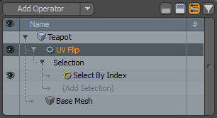
| 3. | Click the Add Operator button, and under Mesh Operations > UV, double-click UV Flip. |
This adds the UV Flip mesh operation to the list and opens its properties in the Properties panel.
You can expand the UV Flip mesh operation in the list by clicking the arrow ![]() in front of it. This reveals the Selection input the operation uses. For more information on procedural selection, see Procedural Selection.
in front of it. This reveals the Selection input the operation uses. For more information on procedural selection, see Procedural Selection.
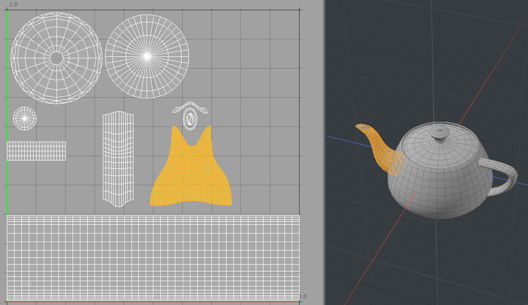
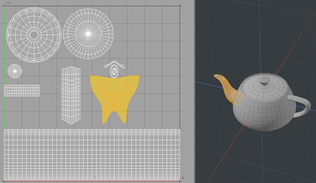
| 4. | Set the Axis along which to flip the selection, and adjust any additional options as needed. For more information on the available properties, see UV Flip Properties. |
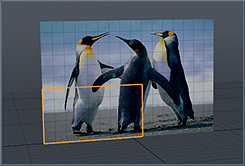
The selected area is flipped along the specified axis. In the image below, Axis is set to V.
UV Flip in the Schematic
You can also work with the UV Flip mesh operation in the Schematic viewport.
Note: For more information on working with Schematic viewport in general, see Schematic Viewport.
To open the Schematic viewport:
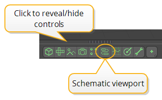
• In the Modo layout, click the thin gray line below the 3D viewport, and click the Schematic viewport ![]() button.
button.
>
MadCap:conditions="Default.NoTranslate">OR
• Switch to the Setup layout from the menu bar by clicking Layout > Layouts > Setup.
To use UV Flip:
| 1. | Click Add..., and under Mesh Operations > UV, double-click UV Flip. |
This adds the UV Flip node to the viewport and opens its properties on the lower right panel.
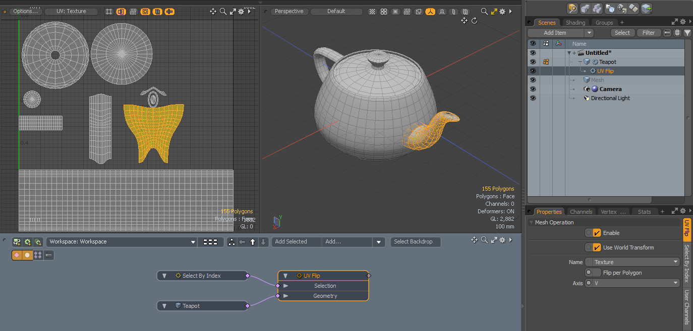
The node has the following inputs:
• Selection - Select polygons or modify your existing selection.
• Geometry - Any geometry that is affected by the tool.
UV Flip Properties
You can adjust the following properties for the UV Flip mesh operation.
| Name | The texture map the UV Flip operation uses. |
| Flip per Polygon | When enabled, the UV orientation is flipped individually for each selected polygon. |
| Axis |
The axis used by the operation: • U - Flips the selection on the horizontal axis, based on the selection's bounding box center location. • V - Flips the selection on the vertical axis, based on the selection's bounding box center location. |