The 3D Viewport
I know you’re itching to start creating, but we still have some important areas of the UI to discuss. Most important is the 3D Viewport (Figure 1.17).
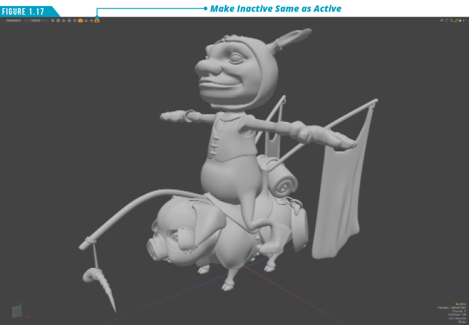
It’s not just located in the center of the interface and the largest area of the workspace by accident. This is where all the magic happens. It’s where you’ll spend most of your time when working in Modo.
This is your virtual workshop where you’ll model, sculpt, paint, rig, animate and more. If there were only one area to focus on, this would be it. You’ll want to get comfortable navigating and customizing the 3D Viewport to get the most out of it. There are many options to customize this powerful viewport, so let’s dive in.
I’ve included a scene file for you to use if you’d like to follow along.
Download the MODO Essentials.zip from the Course Files tab here: https://learn.foundry.com/course/3128/view/modo-essentials
Open (File/Open) the source file Modo_Essentials/Source/S1/Scenes/Gidget_and_Pepperjack_Vaughan.lxo
If you’re using the default settings when the scene is loaded, your viewport won’t match (Figure 1.17). Before we get into the details let’s make one change to get a better look at the mesh items in the scene. In the top left corner of the 3D Viewport, click the icon at the end.
This is the Make Inactive Same as Active option which will display all mesh items in the scene the same, whether they are active or inactive. With that option toggled on, your viewport should match.
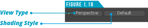
The View Type menu (Figure 1.18) located in the top left corner of the 3D Viewport enables you to change how the scene is viewed. It’s set to Perspective by default, but clicking on the View Type menu enables you to change the view to Top, Bottom, Back, Front, Right, Left, Camera and Light.
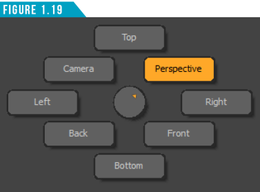
You can bypass the View Type menu by using the keyboard shortcut (Ctrl+Spacebar). This displays the View Type pie menu (Figure 1.19). Hover your cursor over any of the options and release to select a view.
The Shading Style (Figure 1.18) located to the right of the View Type button in the top left corner of the 3D Viewport provides several ways to display the geometry in the scene. These are in-viewport shaders that display the geometry in specific ways, making it easier to visualize certain aspects of a model or scene.
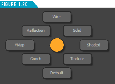
You can also change the Shading Style of the viewport by using the keyboard shortcut (Ctrl+2). This displays the Shading Style pie menu (Figure 1.20).
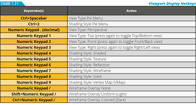
Hover the cursor over the 3D viewport and use the additional hotkeys in (Figure 1.21) as an alternative way of changing the settings.
|
||
|
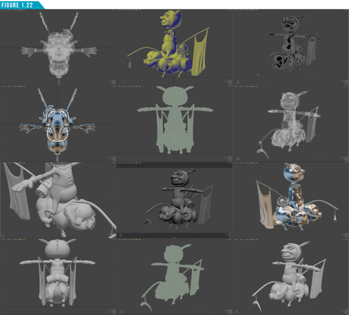
Using what you’ve learned so far, customize the 3D Viewport to match the images shown in (Figure 1.22). Try using the View Type and Shading Style menus, Pie Menus and keyboard shortcuts. Once you’ve completed each of the examples, spend some time combining the various options to get a feel for what works best for you when viewing mesh items in Modo. Note: Gidget and Pepperjack might not appear as large in your viewport as seen in the images below. No worries, we’ll learn how to zoom in and out of the viewport soon. Focus on the View Type and Shading Style for now. |
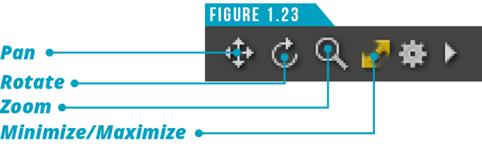
If we were limited to navigating our 3D scene with what we’ve learned so far, we’d have a tough time getting things done in Modo. Fortunately, there are additional functions available that make it easy to navigate the 3D Viewport. The first three icons in the upper-right corner of the 3D Viewport (Figure 1.23) enable you to manipulate the view by panning, rotating and zooming in and out.
It’s important to understand that these are not buttons that toggle on and off. To use them, you left-click and drag over the icons to adjust the view. Give it a try.
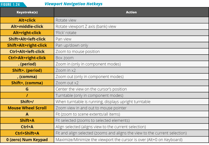
I’ll be the first to admit that it’s not the most intuitive way of navigating the view. My preferred method is taking advantage of the many hotkeys available. Take a look at (Figure 1.24) to see a list of the common hotkeys associated with navigating the 3D Viewport.
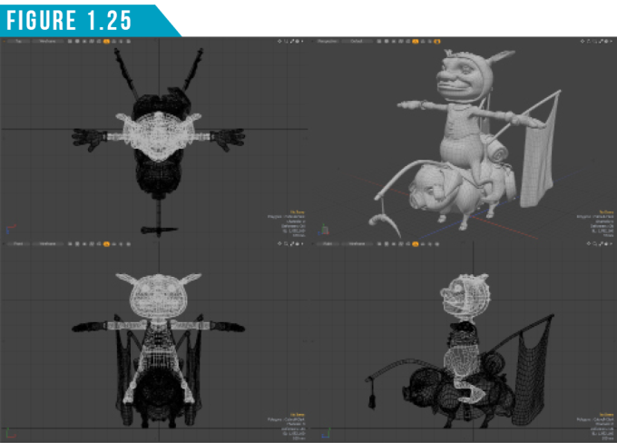
The double-arrow icon next to the zoom icon (Figure 1.23) enables you to minimize and maximize the active viewport. This will convert the 3D Viewport from a single view to a quad view as seen in (Figure 1.25).
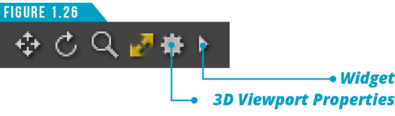
Next to the minimize and maximize icon, you’ll see a gear icon (Figure 1.26). This is just like the gear we talked about for the Layouts Menu, except this contains all the available viewport customization control options for this 3D Viewport.
Clicking the gear icon will open the 3D Viewport Properties (Figure 1.27). You can also open it by hovering your cursor over the viewport and using the keyboard shortcut (O).
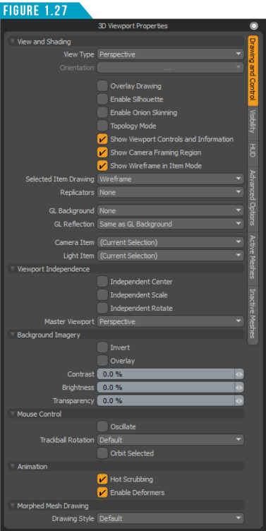
These options give you maximum control over every aspect of the 3D Viewport. We won’t be going over all of these options in this guide, but you now know where the options are located. When you become more experienced with Modo, you can return and customize the viewport to your liking.
Some of the icons located next to the Shading Style button in the top left corner of the 3D Viewport (Figure 1.28) allow for quick access to a few of the viewport settings such as Make Inactive Same as Active, Show Weightmaps and the Replicator Drawing Options.
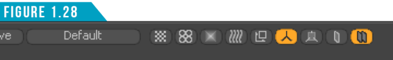
Hovering the mouse cursor over any of these icons displays a tooltip, which is a small text hint with the name of a function or tool, and keyboard equivalents if applicable.
Jumping back over to the upper-right portion of the 3D Viewport, you’ll see a small arrow next to the gear icon (Figure 1.26). This arrow is called the Widget, and for now I’d recommend staying clear of this feature. The Widget Menu allows you to change the viewport to a completely different viewport, which can be useful, but for now we want to keep the default setting and have this viewport remain a 3D Viewport.
In the lower-left corner of the 3D Viewport there is an XYZ axis gizmo (Figure 1.29) that provides a visual reference to the orientation of the 3D space as well as the current Work Plane orientation. We’ll discuss the Work Plane later in this guide.
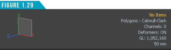
To see the gizmo in action, rotate the view around. This handy feature can help keep you oriented when orbiting a mesh or navigating through a complex scene.
On the opposite side of the 3D Viewport in the lower-right corner (Figure 1.29), several useful bits of information are displayed. Here you can view information that updates dynamically, showing the current number of selected items, the number of live polygons active in your viewport and more.
Last but certainly not least, the Grid that is displayed in the 3D Viewport (Figure 1.30) represents a virtual ground plane. The Origin is located at the center of this grid, and each square represents a fixed distance.
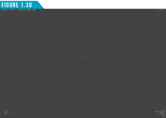
Since this grid is dynamic depending on the zoom level, the display in the lower right corner (Figure 1.29) gives you the real-world equivalent measurements for each square unit, in the case above, it is 50mm.
|
||
|
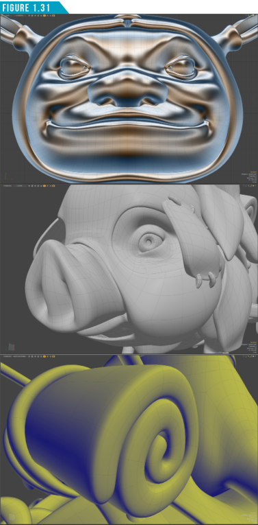
We keep adding new tools to your toolkit. Let’s put them to work. Just like the last exercise, recreate the viewports shown in (Figure 1.31). This will involve many aspects covered so far. If you get stuck, go back and review what has been discussed. Being able to navigate and adjust the 3D viewport will be essential to successfully working in . Spend as much time as you need to feel comfortable before moving on to the next portion of the book. |
Viewport Toggles and Switches
You should now have a basic grasp of working with the 3D Viewport. Modo has additional viewports that you’ll want to use when working on different aspects of a project or production, such as the UV Viewport, which shows you the two-dimensional view of UV space.
This video demonstrates the viewport toggles and switchers, showing how to quickly customize your workspace for maximum efficiency.
In previous versions of Modo, we would use the Layout Menu to switch to a completely separate layout to access the UV Viewport, but the Modo layout gives us easy access to all the viewports we’ll need.
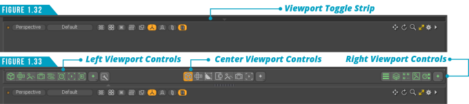
Just above the 3D Viewport is a thin dark strip that highlights when you mouse over it (Figure 1.32). Clicking this reveals the Viewport Switcher Bar (Figure 1.33). The icons in the center of the Viewport Switcher Bar enable you to quickly convert the 3D Viewport into alternate viewports such as the UV, Topology, Camera and Progressive Render Viewport.
The button with the plus sign (+) gives you access to three additional options that you can customize to your liking. Spend a minute clicking each of the center options to see how quickly you can convert the viewport to a variety of viewports. Don’t worry, you wont break anything. Clicking the cube icon that is highlighted in (Figure 1.33) will return you to the default Model Viewport we’ve been working with.
There are many times that I want to work with multiple viewports at the same time. I personally like to have my 3D Viewport visible when working with the UV view, for example. I find it useful to select the edges that will define my UV seams.
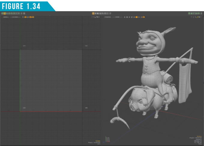
The group of icons on both the left and right side of the Viewport Switcher Bar enables you to split the viewport workspace into multiple spaces. Give it a try. Click on the second icon from the left group to open the UV Viewport. Your workspace should look like (Figure 1.34).
Clicking the same button again will close the left viewport. There is also a Lower Viewport Toggle Strip (Figure 1.35) that, when clicked, displays the Lower Viewport Switcher Bar (Figure 1.36).
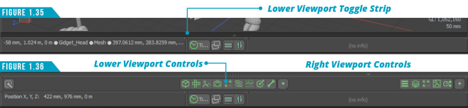
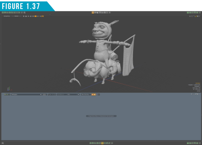
Clicking the fifth icon from the right in the center group of icons displays the Schematic View in the lower viewport (Figure 1.37).
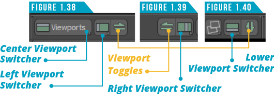
You don’t need to have the center or lower viewport switcher bars visible to access these additional viewports. You can use the Viewport Toggle Controls found in the upper-left corner of the interface (Figure 1.38), upper-right corner of the interface (Figure 1.39), and the lower-left portion of the interface (Figure 1.40).
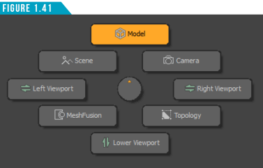
These controls allow you to quickly customize your workspace with multiple views. My favorite option, and the one I use the most, is the Viewport Switcher Pie Menu (Figure 1.41). To activate this handy pie menu, use the keyboard shortcut (Alt+Spacebar). Viewport Switcher Pie Menu enables you to quickly toggle the left, right and lower viewports as well as switch the center viewport to five of the most common viewport options; Model, Scene, Camera, MeshFusion and Topology.
Using the viewport toggles and switchers will enable you to quickly customize the viewport, allowing you to stay in a single layout. It may sound trivial, but it truly does save time and allows you to work more efficiently.
Spend some time exploring these options before moving forward with this guide. Try different combinations of viewports as well as viewport types. Get comfortable using all of the methods discussed and see what works best for you. Remember, everyone works differently, so what works for me may be different than what works for you.