Selection in Modo
Throughout any given work session in Modo, you’ll need to make selections in order to manipulate items (Meshes, Lights, Camera, etc.) and components (vertices, edges and polygons). In this section we’ll take a brief look at the different selection modes, making selections, and useful selection features available in Modo. I’ve included another scene file for you to use if you’d like to follow along.
Download the MODO Essentials.zip from the Course Files tab here: https://learn.foundry.com/course/3128/view/modo-essentials
Open (File/Open) the source file Modo_Essentials/Source/S2/Scenes/CrunkCar_Vaughan.lxo
This video takes a quick look at selecting items in the Items List and 3D Viewport.
Selection Modes
As we learned in the previous section, there are ten core selection modes in Modo, and nine of them can be enabled from the Selection Modes portion of the Modo Modes bar as seen in (Figure 2.1).
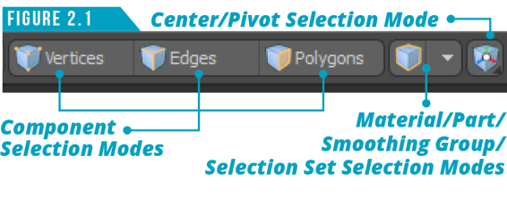
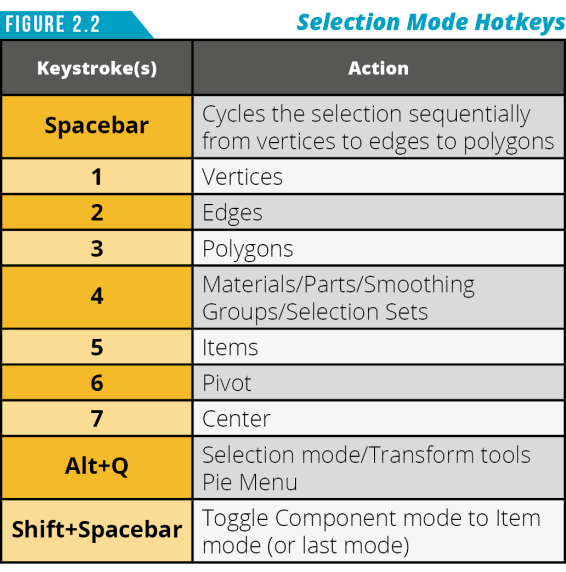
You can only access nine of the selection modes from the UI because by default, Item Selection Mode is enabled, and when not in one of the other nine modes, Modo defaults back to Items Selection Mode. Try and take advantage of the shortcut keys shown in (Figure 2.2) when possible to speed up switching between selection modes.
Since we are already in Item Selection Mode, let’s look at selecting items.
Selecting Items
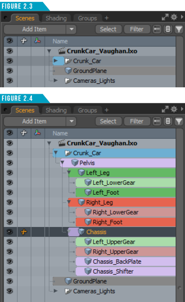
Modo scenes are made up of a collection of items: meshes, cameras, lights, locators, and so on. Items are also referred to as layers. You can tell Modo what items (Layers) you’d like to edit by selecting them. One option for selecting items is to use the Items List in the Lists Viewport. (Figure 2.3)
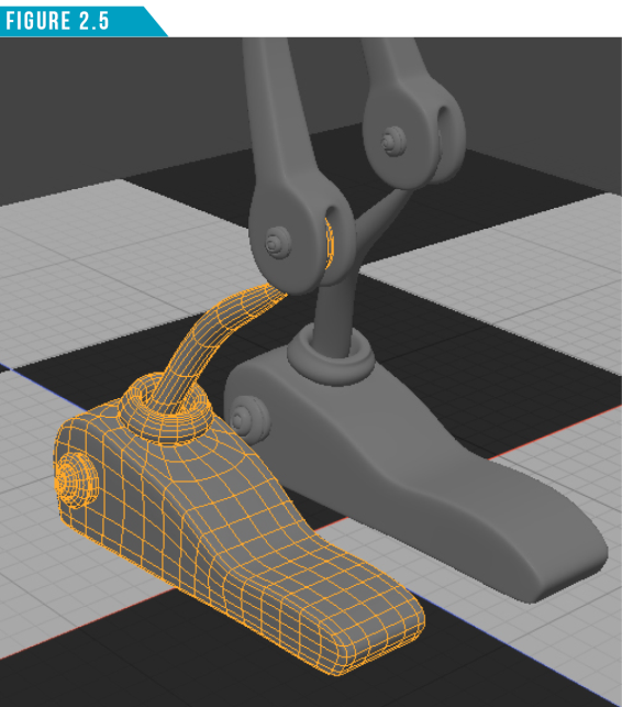
If you hold down the (Shift) key and left-click on the small arrow next to the item named Crunk Car, the entire hierarchy of items will expand. (Figure 2.4)
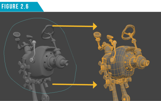
Left-clicking on any item in the Items List will select it. Give it a try. Left click on the mesh item named Right_Foot. The item will become selected and highlighted in both the Items List and the 3D Viewport. (Figure 2.5) As you can see, this can be a quick way to select items in your scene.
Note: It’s always a good idea to give each item in your scene a unique name to be able to identify it quickly. To change an item’s name simply right click on it in the item’s list and choose Rename. It will save you time and frustration if everything in your scene is named properly.
Selected items will appear darker than nonselected items in the Items List, and the item name text becomes orange. Selected items are considered active or foreground layers. Items that are visible, but not selected, are considered inactive or background layers. Background layer name text appears as plain black text.
It’s important to remember these naming conventions because Modo uses both in different parts of the software. For example, the Boolean operation uses the Foreground/Background convention while the 3D Viewport Properties uses the Active/Inactive convention. This can be confusing so be sure to take note.
To select multiple items at once, use the standard Ctrl and Shift key modifiers. Ctrl clicking on a selected item will deselect it without deselecting other selected items. Spend a moment selecting the different items that make up the Crunk Car by selecting them in the Items List.
It would be incredibly limiting if we could only make selections from the Items List. Fortunately, we can make selections directly in the 3D Viewport. There are two main selection styles in Modo: Paint and Lasso.
You can simply left-click on an item in the 3D Viewport to select it, or you can use the Paint Selection style by left-clicking and dragging over items in the 3D Viewport. Give it a try. Start by left-clicking away from any items in the viewport and then left-click and drag over the items that make up the Crunk Car.
Modo selects all items under the cursor as you move the cursor on the screen. In this manner, you can quickly “paint” a selection by dragging over a desired component. Pressing and holding the Shift key as you select items will add them to the selection. You can either Shift-click individual items or Shift-drag across multiple items to add them to your selection. Ctrl-clicking will remove items from the selection.
The easiest way to deselect (Drop Selection) the current selection is to click any empty area in the 3D viewport or press the Esc key.
It’s good to know that making selections is an undo-able action. You can easily undo (Ctrl+Z) a selection state if you accidentally clear a selection.
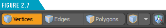
The Lasso Selection style can be performed by right-clicking and dragging to enclose the items within a lasso as seen in (Figure 2.6). There are four different Lasso Styles you can work with: Lasso, Rectangle, Circle and Ellipse.
To change the Lasso style, go to (Select/Lasso Style) in the Application Menu. You can also access these options by right-clicking in the 3D Viewport and choosing Lasso Style from the contextual menu.
Selecting Components: Vertices, Edges and Polygons
It’s important to understand that the component selection modes only apply specifically to Mesh Items. Other items such as Lights, Texture Locators, Replicators or Cameras can only be edited while in Items Selection Mode.
Components (Vertices, Edges, Polygons) are the elements that make up a mesh item. Think of a Mesh Item (Layer) as a container that holds the elements. In order to select these elements, the mesh item needs to be selected.
Selecting Vertices
To be able to select vertices on the Chassis of the Crunk Car, start by selecting the Chassis mesh item either in the 3D Viewport or the Items List. Next, click on the Vertices Selection Mode button in the Modo Modes Bar (Figure 2.7).
Warning: When nothing is selected while in component mode, Modo considers everything selected for active mesh items.
Didn’t mean to scare you with the warning above, but it’s something you’ll always want to keep in mind. Again, when nothing is selected while in component mode, Modo considers everything selected for active mesh items. One benefit of this setup is that dropping your selection is a quick way to select everything.
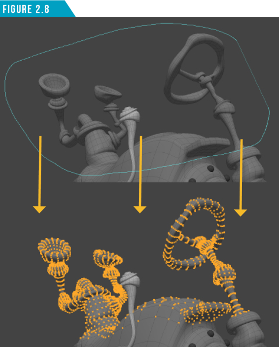
A Vertex is a single point that represents a position in 3D space. Using the same selection options that we used for selecting items (Paint/Lasso), select some vertices on the Chassis. In (Figure 2.8) I used the Lasso Selection method to select some verts.
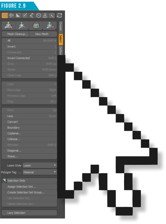
Modo provides a wide array of selection options to use while in component selection mode such as the Loop Select, Invert Selection, Select Connected and Select More/Less functions. You can access these options from the Application Menu (Select) or from the Model Toolbar as seen in (Figure 2.9).
Spend a few minutes exploring the Selection options and selecting different vertices in the Chassis before continuing. Remember, the more hands on practice you get now, the more familiar it will be during production.
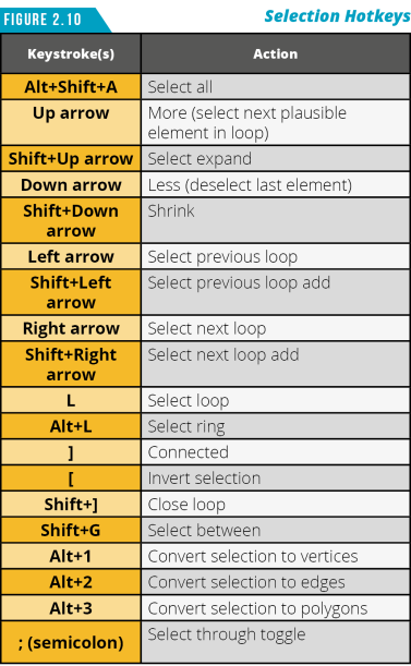
If you want to speed up the selection process, use the Selection keyboard shortcuts shown in (Figure 2.10) to explore some of these useful selection options. Use these shortcuts while in Vertices, Edges and Polygons Selection Mode.
Note: I know I keep throwing lots of keyboard shortcuts at you throughout this guide. Don’t feel like you must memorize all of them. I certainly don’t have all of them memorized, but I have enough that it makes me a more efficient Modo artist.
Selecting Edges
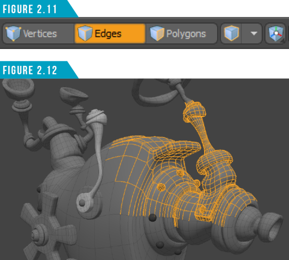
The line between two vertices (verts) is an edge. When in Edges Selection Mode (Figure 2.11), you can use the same paint and lasso selection methods to quickly select one or more edges of the active mesh item(s). Modo indicates selected edges with an orange color to distinguish them from unselected edges. (Figure 2.12)
Selecting Polygons
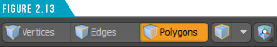
A polygon is a closed plane that is created from three or more edges to create the surface that is shaded and rendered. You can also use the same paint and lasso selection methods you’ve been using. Click the Polygons button to switch to Polygons Selection Mode (Figure 2.13).
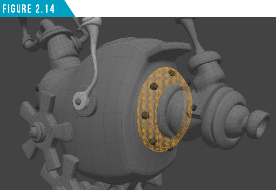
Just like vertices and edges, Modo indicates selected polygons with an orange color to distinguish them from unselected polygons (Figure 2.14).
Using the Spacebar hotkey, toggle through the three component selection modes. As you can see, all your selections remain. This can be incredibly useful when working on mesh items.
Another handy selection option is the double-click shortcut. If you double-click on a vertex or polygon it will be the same as using the (]) hotkey to Select Connected. Try it on one of the rivets that are in the Chassis mesh item. Double-clicking on an edge will perform an edge-loop selection (L).
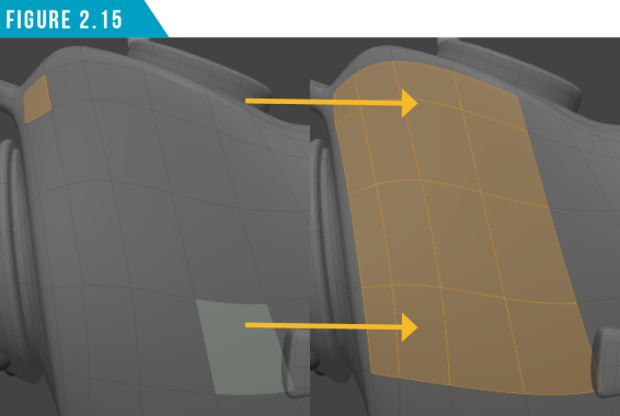
Making a selection, hovering the cursor over another element and then Shift+Right-Clicking will perform a Select Between (Shift+G) operation as seen in (Figure 2.15). You’ll find yourself doing a lot of selecting while working in Modo, so the more you can incorporate these shortcuts into your workflow, the quicker you’ll be at accomplishing tasks.
|
||
|
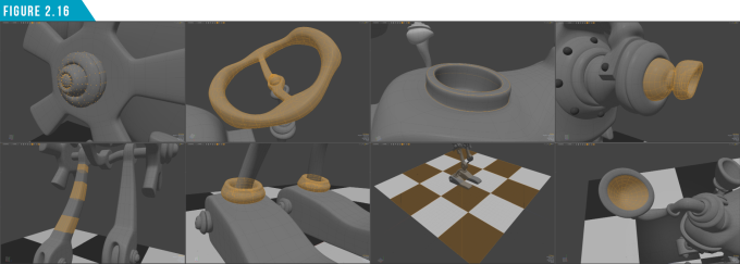
Let’s put your new selection skills to the test and select some components. Using any selection methods you’ve learned so far, match the selections shown in (Figure 2.16). This will also let you take advantage of your viewport navigation abilities. |
Even though we covered it in the Modo Modes portion of Section 1, I want to remind you about Auto Select Mode. Auto Select Mode (Figure 2.17) allows you to quickly change the current component selection mode used in your scene.
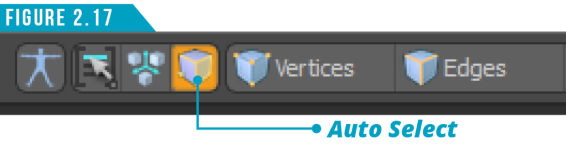
When enabled, you can select a vertex, an edge, or a polygon to automatically activate the different selection modes. For example, if Vertices selection mode is active and there are no vertices currently selected, clicking on an edge will switch to Edges selection mode automatically.
Implicit Selections for Component Modes
In all modes, if you don’t select anything directly, Modo implicitly selects all vertices, polygons, or edges. If you make a direct selection of vertices, only vertices are selected. If you select Edges, vertices of the selected edges and the edges are selected. The vertices won’t appear as being selected in the viewport, but you will be able to perform vertex operations on them.
When polygons are selected, the vertices of those polygons will be implicitly selected as well as the contour edges of those polygons. Again, you won’t see them selected in the viewport, but you’ll be able to perform vert and edge operations while in polygons selection mode.
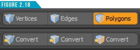
When pressing the (Alt) key and clicking on the component selection mode buttons, you can convert implicit selections to actual selections. (Figure 2.18) shows how the component buttons will change their display while the (Alt) key is held down.
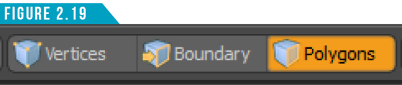
Pressing (Ctrl) changes the Edge Selection Mode button to a Boundary button (Figure 2.19), enabling you to convert the current polygon selection to a boundary-edge selection.
Pressing (Shift) changes the Edge Selection Mode button to a Bounds button (Figure 2.20), enabling you to convert the current polygon selection to a boundary-edge selection without losing any edges that are already selected. So Bounds is an additive conversion while Boundary isn’t.

Spend some time exploring these implicit selection conversion options. They are incredibly useful, and I find myself using them on a regular basis. While you have either the Alt, Ctrl or Shift key pressed, have a look around the UI to see how other buttons take advantage of hidden options using key modifiers.
Selecting Materials
We haven’t discussed materials yet, but I have some predefined materials on the Crunk Car we can use to explore material selection. Materials are defined by selecting polygons and assigning a Material Tag. These tags produce a Material Group Item in the Shader Tree that represents the tagged polygons for masking. We’ll go into further detail about this later in the guide.
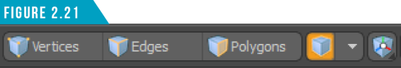
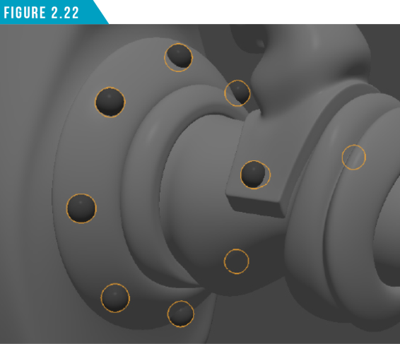
When Material Selection Mode is enabled (Figure 2.21), you can directly select the geometry based on the Material Tag.
Modo indicates material selections as orange outlines surrounding the area defined by the tags. (Figure 2.22) You can either use the selection to edit the geometry or adjust the surfacing within the Shader Tree.
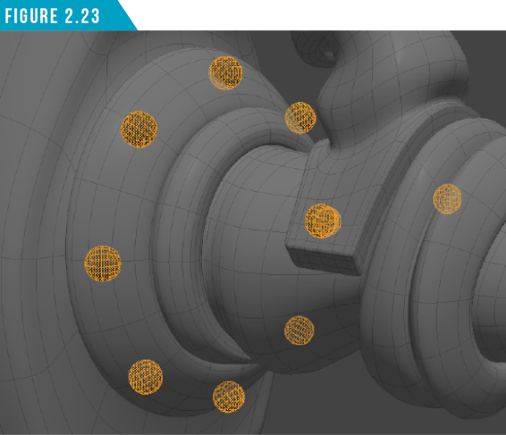
I use material selections to quickly convert to polygon selections. Give it a try. Select the Rivets material on the Chassis mesh item using Material Selection Mode and convert the selection to a polygon selection. You should end up with all the rivets on the Chassis mesh item selected. (Figure 2.23) That’s a much faster way of selecting all those polygons than Shift+Double-Clicking them.
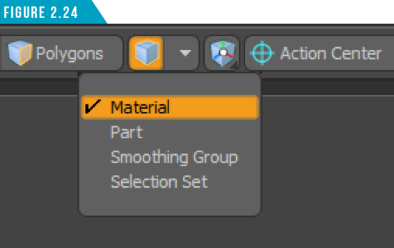
The Material Selection Mode isn’t limited to selecting Material Tags. You can specify the Materials selection mode to be based on Material, Part, Smoothing Group or Selection Set tags. Simply choose which tag type you’d like to select from the menu as seen in (Figure 2.24).
This is an often overlooked selection feature so be sure to keep it in mind for future use! I didn’t discover this was even an option until five years of working with Modo, and I’m finding that many Modo artists are unaware of it as well. It’s a reminder that there are always new things to discover when working with software.
Selecting Centers
The Center element represents the center location of a Mesh Item. Each Mesh Item in the Items List has its own center position. Modo uses this as the origin for all Position, Scale and Rotate transforms for that Mesh Item (layer).
By default, the Center is located at the World Position Origin of 0,0,0 for all mesh items. In the case of the items that make up the Crunk Car, all centers have been repositioned to enable the parts to rotate from the correct location for animation.
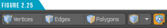
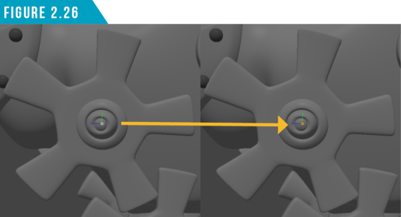
When Centers Selection Mode is enabled (Figure 2.25), you can select an Item’s center by clicking the center icon in the 3D Viewport.
Modo indicates a Center is selected by changing the white filled circle to an orange filled circle icon as seen in (Figure 2.26).
Warning: Modo’s Centers are often called “Pivots” in other software. I’ve seen this cause confusion with artists coming over from other software.
Selecting Pivots
As mentioned in the warning, Modo’s Centers are often called “Pivots” in other software. In Modo, a Pivot is a secondary center-like element that is offset from the center. If you modify the pivot’s position, then that pivot position becomes the animation origin and overrides the center position.
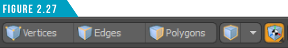
The key difference of pivots and centers is that you can use a keyframe to animate a pivot position, but you can’t animate a center. Pivot Selection Mode (Figure 2.27) can be enabled by right-clicking on the Center Selection Mode icon and choosing Pivot.