Working with Tools
Having successfully made it this far, you are now ready to perform actions on your selections. Modo offers an array of one-shot commands and interactive tools that enable you to create and manipulate geometry. Let’s start by taking a quick look at the difference between one-shot commands and tools. Use the keyboard shortcut (Ctrl+Shift+W) to Close All open scenes.
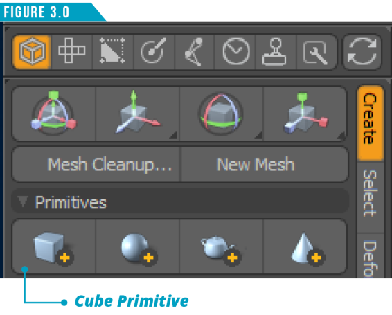
You will be left with a default scene consisting of an empty Mesh Item, a Camera and a Directional Light. Hold down the Shift Key and click on the Cube Primitive Button in the Model Toolbar (Figure 3.0).
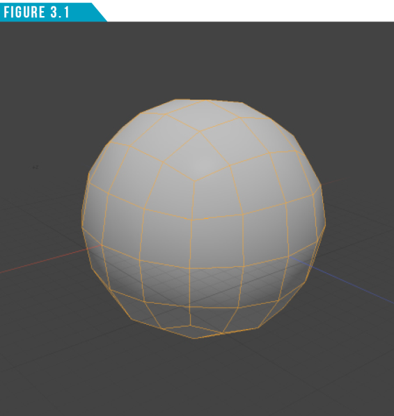
This creates a 1 Meter cube in a new Mesh Item named Cube, located at the Origin. Note that we were given no options for the scale or placement of the Cube. Press the keyboard shortcut (D) twice to Subdivide the cube (Figure 3.1). Use the Keyboard shortcut (Ctrl+Z) to Undo the last Subdivide command.
Everything you’ve done since the start of this section used one-shot commands. There are many features in Modo that are one-shot commands that when executed, perform their function such as creating geometry or undoing actions as you’ve just experienced. Some one-shot commands may display a dialog, allowing you to define attributes of the command.
For example, switch to Polygon Selection Mode, and then use the keyboard shortcut (Shift+D). This brings up the Subdivide Polygons dialog (Figure 3.2).
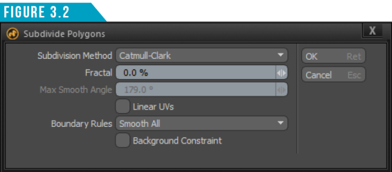
Select Catmull-Clark as the Subdivision Method and click OK. The result should be the same as before you performed the Undo command. One-shot commands offer no real interactivity. You simply click the button to produce a result.
Clicking on an interactive tool’s button makes the tool active but then waits for you to provide further instructions. Let’s see this in action. Click the Move Tool Button (Figure 3.3) to activate the Move Tool.

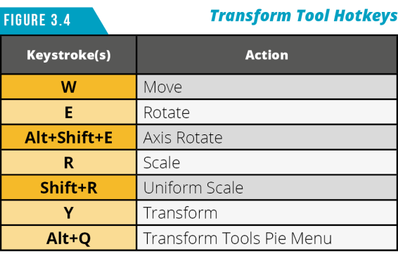
The Move Tool is a standard transform tool that you’ll frequently use in all aspects of Modo. From here on out, I’d recommend using the keyboard shortcut (W) to save time. Use the shortcuts shown in (Figure 3.4) for additional transform tool hotkeys.
When interactive tools are activated, you have a couple options for how to interact with them. The first option is modifying the tool’s attributes using the Tool Properties Panel. To do this, we need access to the panel.
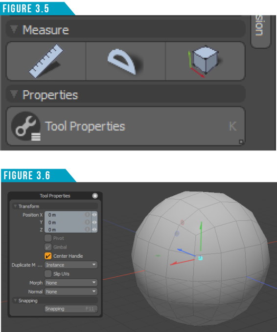
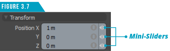
Use the keyboard shortcut (K) or click the Tool Properties Button at the bottom of the Toolbar (Figure 3.5). I’m sure by now you can guess which method I prefer. Using either method will display the Tools Properties Panel (Figure 3.6).
You might have noticed a colorful red, green and blue handle appear in the 3D Viewport. We’ll get to that in a moment, so disregard that for now.
Numeric attributes can be edited by simply clicking directly on the value and then entering a new value with the keyboard. When you’re happy with the value, press Enter to accept. Let’s give it a try.
Give the Position X attribute a value of 1 and press Enter. This moves the entire subdivided cube 1 meter in the positive X axis.
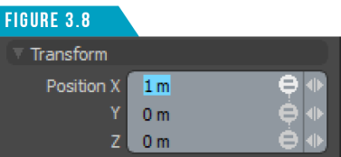
You can also modify numeric values interactively using the mini-sliders (small white arrows) that appear on the far-right hand side of most numeric entry fields (Figure 3.7). By clicking and dragging on the mini-sliders, you can quickly increase (dragging right) or decrease (dragging left) the current value in the field.
If you’d like to edit all three values, you can use the gang edit options by clicking the icon to the left of the mini-sliders. The first click will change the icon to an equal sign (=) (Figure 3.8), which will apply identical values to all three attributes (Copy).
The second click will change the icon to a proportional symbol (α) (Figure 3.9), causing all value changes to be applied proportionally (Proportional).

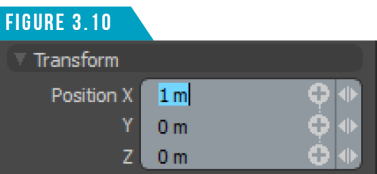
The third click will change the icon to a plus sign (+) (Figure 3.10), and the value will be added to the attributes (Relative).
Clicking a fourth time will return the icon back to it’s original state, and all attributes will be edited independently.
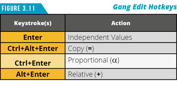
I prefer using the keyboard shortcuts shown in (Figure 3.11) when using these options.
Tip: Numeric input fields can be used as tiny little calculators. They allow you to enter simple equations, and the value is computed automatically.
For example, you could enter 2+4*8/2 and Modo would calculate the result of 18 Meters.
Accepted symbols: (/) divide, (*) multiply, (-) subtract, and (+) add.
When you’re happy with the values you’ve entered, press the keyboard shortcut (Q) to Drop the Active Tool. You could also click the Move Tool Button again to drop the tool, but save yourself the time and use Modo’s universal shortcut key that will work with all tools without having to click the button again.
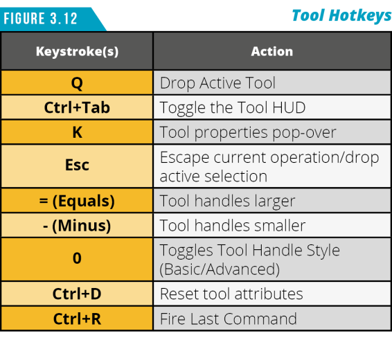
Take advantage of the additional tool-related keyboard shortcuts shown in (Figure 3.12). Let’s look at working with the Move Tool in the 3D Viewport.
This time, instead of manipulating the entire subdivided cube, select the top polygons. Activate the Move Tool (W), left-click on the Y Axis Handle (Green Arrow) and drag up as seen in (Figure 3.13).
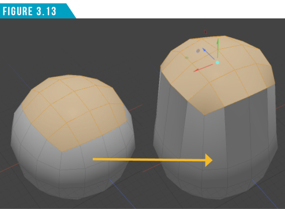
As you can see, we can change values by clicking and dragging on any of the available tool handles (handles change to a yellow color to show they can be adjusted), constraining the action to a specific axis.
Press (Q) to drop the Move Tool.
By Selecting the top polygons, we limited the movement to only those specific elements. This is how we can manipulate geometry into custom shapes. You can also limit the effect a tool has on a mesh item using the Hide and Lock features.
Modo enables you to modify the visibility of items in the Items List Viewport by clicking on the Visibility Toggle (Eye Icon). You can also hide portions of a mesh item by using the keyboard shortcuts shown in (Figure 3.14).
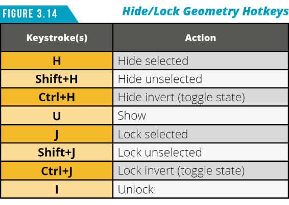
If you want to have the geometry remain visible but restrict it from being edited, use the Lock commands, which are also shown in (Figure 3.14).
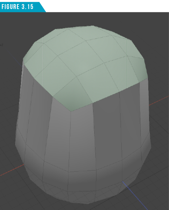
Locked geometry will be shaded differently in the 3D Viewport, as seen in (Figure 3.15).
Tool Handles
We experienced using the Y Axis handle for the Move Tool and how it restricted the movement of the selected geometry to a single axis. Let’s take a closer look at the anatomy of tool handles. Different tools have different handles (Viewport Manipulators/Gizmos), so we’ll take a look at a few examples so you understand the basic handle conventions used in Modo.
The Move Tool
Activate the Move Tool (W). The Move Tool Gizmo (Figure 3. 16) consists of seven handles. The main handles are the red, green and blue arrow handles which are used to restrict the movement to the X (Red), Y (Green) and Z (Blue) axes.
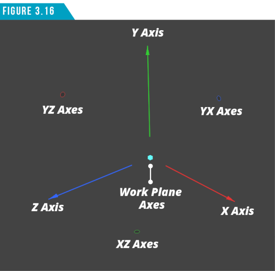
The red, green and blue circular handles are planar handles that I also refer to as paddles. These handles enable you to move in two axes at the same time. For example, using the red paddle restricts you to the two axes that are perpendicular to the X axis, which are the Y and Z axes.
The cyan (light blue) handle in the center updates dynamically as you rotate around your scene, restricting the movement to the two axes perpendicular to the Work Plane. When the Work Plane isn’t visible, use the XYZ axis gizmo in the lower left corner of the 3D Viewport as a reference for where the Work Plane is at any given time.