Rigging and Animation
When you’re ready to animate a 3D asset, Modo offers a variety of tools and functions for rigging. Rigging is the process of creating controls that aid in the manipulation of items in a scene. Think of a marionette puppet that is controlled from above using strings. With just a few subtle hand movements, the puppet can be brought to life.
This video takes a quick look at Rigging and Animating in Modo.
In this section we’ll look at creating a basic vehicle rig that will enable us to save time when animating. I’ve included a scene file of a carton truck that you’re free to use if you’d like to follow along.
Download the MODO Essentials.zip from the Course Files tab here: https://learn.foundry.com/course/3128/view/modo-essentials
Open (File/Open) the source file Modo_Essentials/Source/S8/Scenes/Truck_Vaughan.lxo
Just like we’ve done in previous sections, let’s adjust our workspace to gain access to tools and viewports that will speed up the rigging process.
Switch to the Setup Toolbar using the fifth icon from the left in the Toolbar Menu. Next, use the Viewport Switcher Pie Menu (Alt+Spacebar) to open the Lower Viewport, and then switch the lower viewport to the Schematic Viewport. Your workspace should look like (Figure 8.0).

To enable the wheels and the truck to move together but remain independent of each other, we’ll create a locator that they can all be parented to. In Modo, a locator plays many important roles in rigging and animation, as they can be used as targets, controllers, parents, manipulators, selectors, and more. Click the Create Locator Button (Figure 8.1) in the Setup Toolbar to add a locator to the scene.

A new locator will be added to the scene at the origin. Move it to the top of the Items list by left-clicking on it and dragging it to the top of the list.
Next, select the Truck and Wheel mesh items and left click and drag them on top of the locator to parent them to the locator (Figure 8.2).
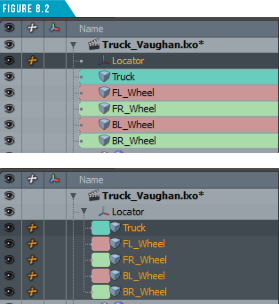
By default, a locator looks like an asterisk, but we can change the look of a locator by changing its display properties. Select the locator in the Items List and rename it (Truck_Mover).
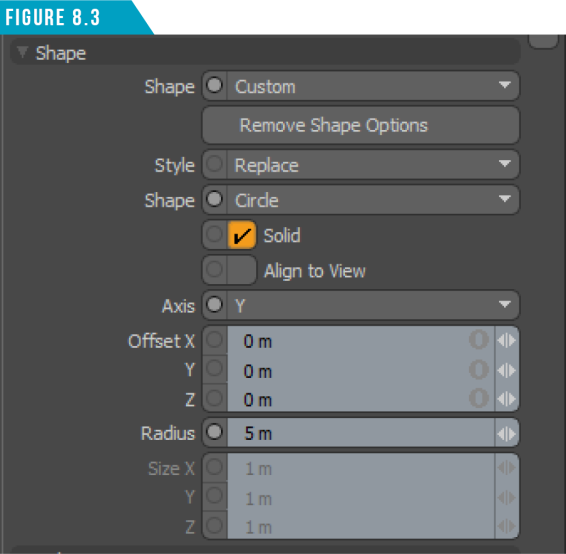
In the Properties Viewport, change the Shape attribute to (Custom). This will reveal additional attributes. Next, change the Shape to (Circle), the Axis to (Y), and the Radius to (5m) (Figure 8.3).
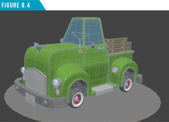
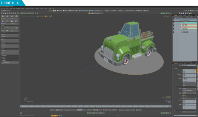
Your locator should now look like (Figure 8.4). This will make it easier to see and select in the 3D viewport.
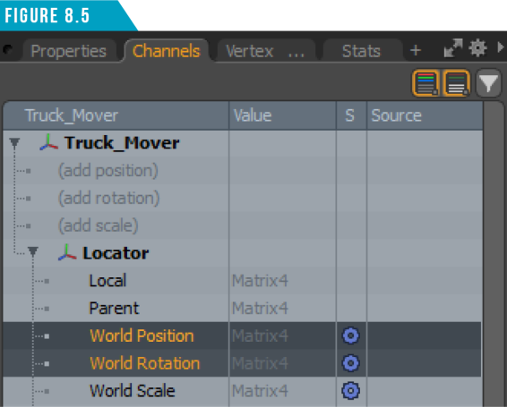
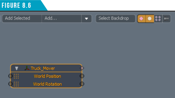
With the locator still selected, open the Channels Viewport (to the left of the Properties tab), and then shift-select (World Position and World Rotation) (Figure 8.5).
With both channels selected, right-click and choose (Add Channel to Schematic). A new node will be added to the Schematic Viewport (Figure 8.6).
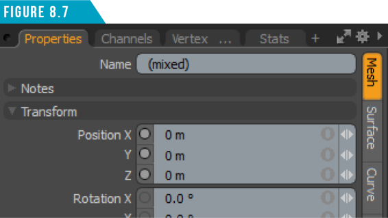
Select all four of the wheel mesh items, open the Properties Tab, and then locate the Rotation X channel attribute (Figure 8.7).
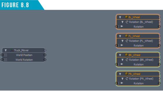
Right-click on the Rotation X channel attribute name and choose (Add Channel to Schematic). Four new nodes will be added to the Schematic View. Spend a minute organizing them by left-clicking and dragging them into place (Figure 8.8).
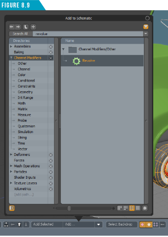
Click the (Add...) button in the Schematic Viewport and locate the (Revolve) channel modifier. The fastest way to do this is to use the (Search All) field at the top of the browser (Figure 8.9).
Double-click (Revolve) to add it to the Schematic View (Figure 8.10).

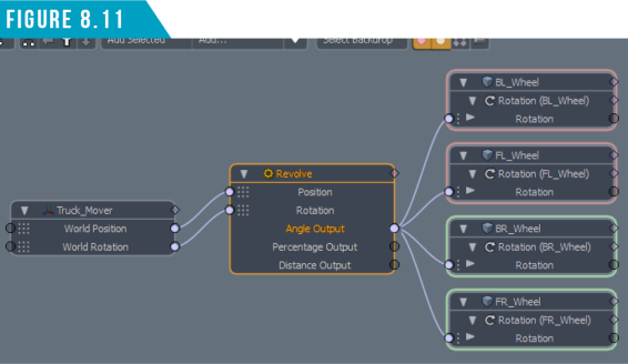
To make connections in the Schematic Viewport, you simply left-click and drag on the small circles located on the sides of the nodes. Connect the following channels: (World Position to Revolve Position), (World Rotation to Revolve Rotation) and (Revolve Angle Output to all four Wheel Rotation Inputs). Your Schematic View Should look like (Figure 8.11).
We’re almost done with setting up the rig for this truck. All that’s left to do to get the Revolve channel modifier to produce the correct results is to feed it the radius of the Wheels.
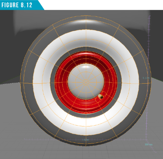
An easy way to get the dimensions of a selection is to activate the Dimensions Tool (View/Dimensions Tool). Next, select one of the wheels and make note of the diameter (Figure 8.12).
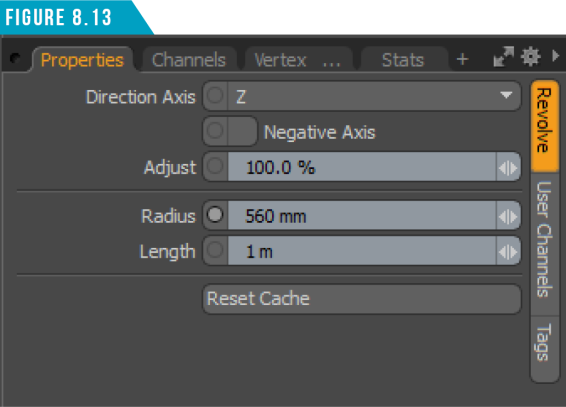
Select the Revolve channel modifier node and enter (1.12m/2) into the Radius attributes input field. Modo will calculate the simple math equation and produce (560mm) to give us the radius of the wheel. (Figure 8.13)
Our truck is now complete and ready to animate. If we’ve done everything properly, all we should have to do is animate the locator we created, and the Truck and Wheels will move with it. All four wheels will also spin the proper amount, which will save us loads of time when animating.
Animating with the Truck Rig
Let’s spend a second adjusting our workspace. Switch to the Animation Toolbar using the sixth icon from the left in the Toolbar Menu.
Next, use the Viewport Switcher Pie Menu (Alt+Spacebar) to close the Lower Viewport, and then disable the Dimensions Tool (View/ Dimensions Tool).
Click the Time Button at the bottom of the UI to open the Timeline Viewport, and then select the (Truck_Mover) locator. Your workspace should look like (Figure 8.14).
To animate the truck, we’ll need to create at least two keyframes. In animation, keyframes are frames in a sequence in which prominent changes take place. You create a “key” at critical positions for an item, and Modo will automatically fill in the frames between keyframes smoothly interpolating the motion.
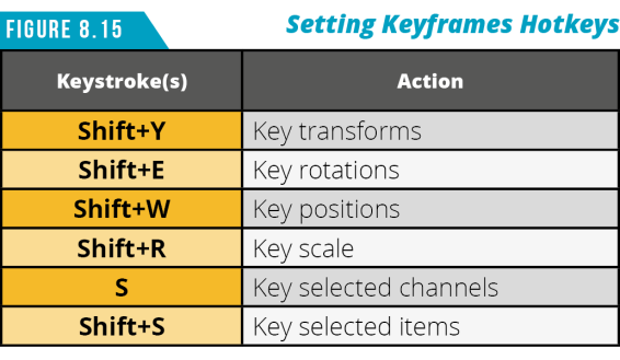
Let’s use the current location of the truck as our starting position. To set a keyframe for the locator’s position channels, make sure you’re in Items Selection Mode and then use the keyboard shortcut (Shift+W). For additional shortcut keys related to setting keyframes, check out (Figure 8.15).
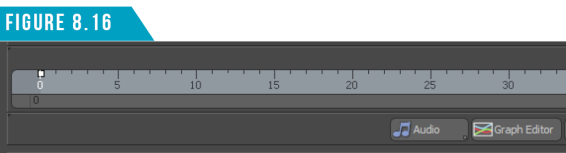
If you look at the Timeline, you should see a small white square on frame zero (Figure 8.16). Congrats! You just created your first keyframe in Modo.
Left-click and drag in the Timeline to move to (Frame 30), and then use the Move Tool (W) to move the locator forward in the (Positive Z).
Take note that the wheels are automatically rotating when the locator is moved, thanks to the rig we created. When you’re happy with the new position of the truck, drop the Move Tool.
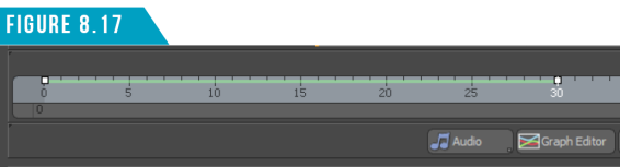
A new keyframe will automatically be created at frame 30. You’ll also see a light green line between the two keyframes that denotes inbetween frames (Figure 8.17).
You can scrub the animation by left-clicking and dragging in the timeline. This can be a quick way of testing portions of your animation while you animate.
Open the Graph Editor by clicking the Graph Editor Button in the Timeline Viewport. Use the keyboard shortcut (A) to fit all selected channels into view.
Select the (Position Z Channel) from the Channel List to isolate that channel for editing (Figure 8.18).
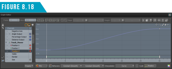
The Graph Editor is an animator’s sniper rifle. It allows you to control not only keyframes, but how Modo interpolates the in-between frames as well. You’ll want to spend some time becoming familiar with both the Timeline and Graph Editor options if you want full control when animating in Modo.
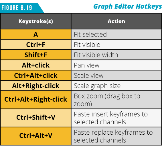
Use the keyboard shortcuts in (Figure 8.19) to help speed up navigating the Graph Editor.
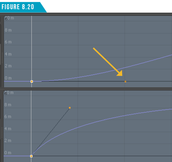
Select the keyframe on (Frame 0) by left-clicking it. Left-click and drag the handle located to the right of the keyframe to adjust the easing-in and out of the curve (Figure 8.20).
It’s important to learn your way around the Graph Editor if you plan on spending time in Modo. Almost every property/attribute of any item can be animated by keyframing the values of an item’s channel. I’ve labeled a few key components in (Figure 8.21) to help introduce you to where some of these important options are.
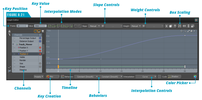
The Channels List on the left side of the Graph Editor are the same channels that appear in the Channels Viewport we’ve worked with on the right side of the UI.
The line (curve) that connects the individual keyframes represents the value’s change over time. By default, Modo uses a smooth curve to interpolate between keyframe values, providing a nice ease-in/ease-out type of effect. There may be times when you want a very different interpolation style, or simply to apply finer control.
Animation curves can only be changed by manipulating the keyframes and are very similar to working with the Bezier Curve Tool in the Model Toolbar. Keyframes are represented as small squares along the line.
The Timeline across the bottom of the Graph Editor is pretty much identical to the Timeline in the main workspace. Clicking and dragging changes the current time. As you drag the current time value around, you can see the effect of the animation curve in the 3D viewport. Handles appear in the Timeline wherever a keyframe appears, and you can click and drag them in time forwards or backwards, modifying the position of the keyframes for selected channels.
If you plan on doing any animation in Modo, you’ll want to take advantage of what the Graph Editor has to offer to avoid stiff, lifeless motion in your animations.
Save your work (File/Save As…), and then download the MODO Essentials.zip from the Course Files tab here: https://learn.foundry.com/course/3128/view/modo-essentials
Open (File/Open) the source file Modo_Essentials/Source/S8/Scenes/Liam_ACS_Rig_Vaughan.lxo
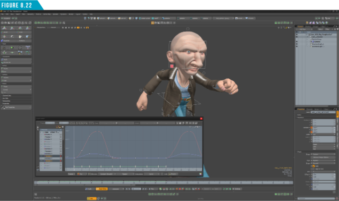
This scene (Figure 8.22) contains a fully rigged character for you to explore. Spend some time selecting the different controls (locators) that make up the rig, and study the keyframes in both the Timeline and Graph Editor. When you’re ready, we’ll continue to the next section of the guide.
|
||
|
You now know enough to be dangerous with rigging and animation in Modo. Use the truck rig you created as well as the provided Liam rig and start animating. The best way to get comfortable doing something is to simply do it. So, start rigging and animating and using the vast collection of tools Modo has to offer. |