Stitching Images Together
CaraVR uses the C_Stitcher to generate a spherical lat-long by warping and blending between the different input images from the C_CameraSolver. See Stitching Stereographic Rigs if you're stitching a stereo rig.
To stitch sequences:
| 1. | Connect a C_Stitcher node to the output of your C_CameraSolver node. |
| 2. | CaraVR automatically adds a single keyframe at the current frame, but you can add keyframes manually by either: |
• scrubbing in the Viewer and then clicking Add Key (![]() ) to add a keyframe at the current frame, or
) to add a keyframe at the current frame, or
• clicking Key All to add keyframes throughout the sequence at the Step interval.
If you have a lot of movement in your sequence, set the Step interval to a lower value so that the greater difference between frames is accounted for in the stitch. The opposite is true for more static sequences, where a higher value may produce better results.
• clicking Import and selecting the node from which you want to import keyframes. You can import keyframes from any instance of C_CameraSolver, C_Stitcher, or C_ColourMatcher in the script.
Note: C_Stitcher only computes optical flow camera warps at designated keyframes, it ignores upstream animation that does not fall on the same keyframes. Use the Import button to copy over all keyframes from C_CameraSolver. This way, any additional per-camera, manual keyframes added in the Cameras tab are also copied.
Adding keyframes manually can help in blurred areas between existing keyframes where the interpolation is inaccurate.
The more keyframes you add, the longer the process takes, though you may get better results. The stitcher warps and blends the input images to create the final warped frames.
| 3. | To see the before and after images, toggle Enable Warps on and off. |
|
|
|
|
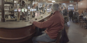
Pre-warp sequence |
The sequence with warp enabled. |
| 4. | Enable Override Cameras to use the Cameras tab in the Properties panel to select which cameras are warped. |
You can view any combination of input cameras in the stitch output by enabling and disabling cameras in the Selected tab. The Preset dropdown can quickly enable or disable all cameras in the stitch by selecting All or None.
For example, if you wanted to examine the stitch between two cameras in isolation, select None from the Preset dropdown and enable the cameras you're interested in.
| 5. | Use the Vectors tab in the properties to control the quality of the vectors used to produce the warp on the input images. |
Higher values tend to produce better warps, but at the expense of compute times.
Note: Vectors are only calculated at keyframes, with faster interpolation taking care of the frames in between. So, the more keyframes you have, the longer the stitch takes.
See Troubleshooting Stitches for more information.
| 6. | Use the Blend dropdown to switch between the default Alpha mode, Multi-Band, and Spherical Multi-Band modes. Multi-Band blending can improve stitch results by matching low frequency color changes over the course of the blend region, but can be slower to process than the default Alpha mode. Spherical Multi-Band blending can improve stitch results at the poles, looking up or down. |
You can use the Suppression control to adjust the amount of blending applied between adjacent views when using Multi-Band blending. Lower values can help balance color and exposure between blended images, higher values are closer to the result from the default Alpha blending mode.
Note: Multi-band blending has no effect on per view C_STMaps exported from C_Stitcher. See Exporting to Preset Nodes for more information on exporting C_STMaps.
If you intend to export C_STMaps, you'll need to enable Multi-Band blending in C_Blender when you merge the separate streams back together. However, the results will not match those output by C_Stitcher because C_Blender uses resampled input images. See Blending Multiple Views Together for more information.
Tip: CaraVR adds a tab to the Properties panel of Nuke's Write node allowing you quickly select groups of views such as stereo and cams when rendering previews or stitches. You can still select views manually using the views dropdown, but View Presets can make the process faster.
Setting the Convergence Point in Spherical Rigs
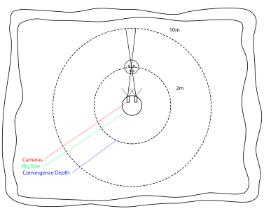
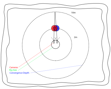
If you're using a spherical camera layout, you can set the Converge control to the depth at which the cameras overlap, allowing you to bring a single point of interest in the scene into focus.
Note: Convergence doesn't have any affect on nodal rigs because all the cameras share the same origin.
Assuming that the cameras sit on a sphere, changing the size of the sphere affects the angle at which the cameras converge. C_Stitcher uses the Rig Size set in C_CameraSolver's Cameras tab to control the sphere. This normalizes the 3D representation of the rig into close to real world units, depending on the quality of the solve. The Converge control then defines the depth at which the stitch is converged, bringing the required point of interest into focus.
|
|
|
|
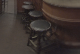
Convergence at 2m |
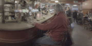
Convergence at 10m |
Setting the convergence point in the foreground may produce ghosting in the background, as shown on the left. The opposite is also true, as shown on the right, where ghosting may appear in the foreground if the convergence point is in the background.
In some rigs, you'll have to compromise between producing a correct stitch in the background with high convergence values and a correct stitch in the foreground with low convergence values.
Tip: If you set the Converge control in the C_CameraSolver, you can automatically import the convergence depth by enabling Auto to the right of the Converge control in the C_Stitcher Properties panel.
The example shows converge depths using the default Rig Size setting of 0.3 (or 30 cm). The Converge control defaults to 10, which is a little high when considering the stools in the foreground.
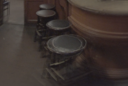
Decreasing the Converge value to around 1.6 metres brings the stool into focus nicely.