Estimating and Removing Lens Distortion Using Lines
Line analysis estimates the distortion from lines drawn manually along features in the input that are known to be straight. This can be useful if there is no grid available or if you have a grid for your sequence but the grid analysis failed, for instance due to bad lighting.
The LensDistortion node has five tools for selecting and drawing features and lines in the Viewer:
|
|
|
Select - a multi-purpose tool used to select, move, and delete features and lines. |
|
|
|
Select Feature - used to select, move, and delete features. You cannot affect lines using this tool. |
|
|
|
Select Line - used to select, move, and delete lines. You cannot affect features using this tool. |
|
|
|
Add Feature - used to add, select, move, and delete features. You cannot affect lines using this tool. |
|
|
|
Add Line - used to add and delete lines. You can connect existing features or create new lines using this tool. |
To estimate lens distortion using lines, do the following:
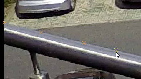
| 1. | Examine the source footage for distorted lines that are known to be straight. If you have a grid, this is simple, but real life examples include walls, railings, roads, and so on. |
| 2. | Select the Add Feature tool and start to add points along the distorted lines by clicking in the Viewer. |
Tip: You can also draw lines immediately using the Add Line tool, but adding features first can be more accurate.
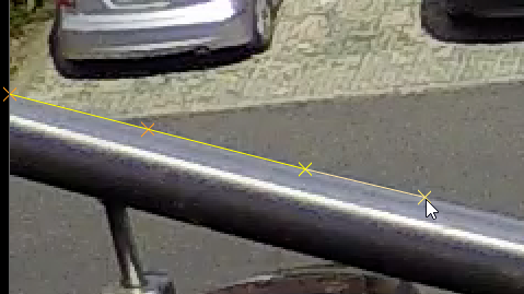
| 3. | When the features are complete for a particular line in the image, switch to the Add Line tool. |
| 4. | Select the first feature in the Viewer and then click the next feature to add a line between the two. |
Tip: When you've finished drawing a line, either select a different tool or press Enter to finish the current line before starting another.
Tip: You can adjust the position of features and lines using the selection tools in the Viewer.
| 5. | The solve requires at least as many lines as there are Distortion Parameters to calculate the distortion. In the case of NukeX Classic, two vertical and two horizontal to cover the Denominator and Centre parameters. Good line drawing practices include: |
• Drawing lines with three or more features - lines with only two points are ignored.
• Drawing longer lines - they contain more useful information on the curvature resulting from lens distortion.
• Distributing lines evenly - avoid biasing the solve by covering as much of the image as possible.
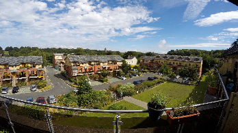
The following example shows a typical set of lines.
|
|
|
|
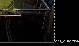
The original distorted shot |
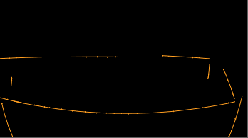
Example lines in the alpha channel |
| 6. | Click Solve to calculate the distortion, there's no need to run the Detect step with manual features and lines. |
Green lines represent links that fall within the Threshold value and red lines those that fall outside the Threshold. You can hover over links to display their solve error.
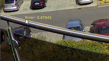
Tip: Clicking Solve again can improve the result in some cases.
| 7. | When you're happy with the solve, switch the Output Mode to Undistort. |
Note: You can also output the distortion as an STMap for use in other images. STMaps contain the pre-computed warp data in the motion channel, allowing you apply the warp quickly and easily. See Working with STMaps for more information.
Nuke takes the estimated distortion and uses the result to 'straighten' the feature links.
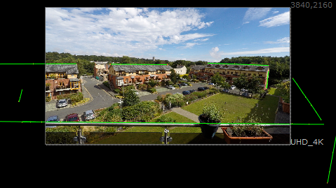
You may notice that the lines expand beyond the bounding box of the footage, which can mean you're losing image data.
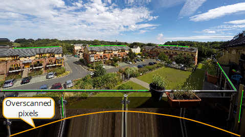
| 8. | Set the Format control to Reformat and select a larger format to include the grid. For example, if your original grid is UHD_4K, you might reformat to 8K_LatLong. |
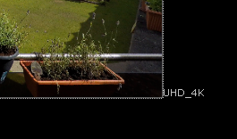
Reformatting the feature lines deforms it into a characteristic bow tie shape. Any areas of the image where there is no data are overscanned, meaning the last pixel available is duplicated to the edge of the format. The area at the bottom of the image in the center shows overscan.
You can now apply your VFX work before redistorting the plate back into its original state.
| 9. | If you don't want to reformat the image, or only a small amount of the image is missing, you can bring more image data into the format bounds using the Adjust Format controls. |
| 10. | Enable Override and then use the Add Pixels and Adjust Aspect controls to enlarge the format as required. |
Note: You can use expressions to control the number of pixels added as a percentage of the format by right-clicking the Add Pixel control and selecting Add Expression. For example, input.width*0.05 adds pixels equal to 5% of the input format's width.
|
|
|
|
The undistorted format |
The adjusted format |
The new format is called lens_distortion_adjusted by default, but you can enter any name you choose in the adjustedFormatName control. The new name is then added to the Project Settings > Format dropdown after adjustment to avoid changing Nuke's default formats.
Tip: You can also preserve overscan data by increasing the bounding box. The Add Pixels control allows you to add an equal number of pixels on all sides of the image or you can edit the bounding box manually by enabling Override and using the outputBBox controls.
| 11. | You can now track, matchmove, composite, and so on in the undistorted space before redistorting the image. See Applying Lens Distortion to an Image for more information. |