Constraining Prims
Constraining allows you to link the transformations or two or more prims together. In Nuke, this is done either by the GeoConstrain node, or via the constraint input and Constrain tab options in various other nodes, as outlined below.
Using GeoConstrain Node
The GeoConstrain node allows you to constrain geometry, cameras, lights, and more, to other prims in your scene.
| 1. | Add a GeoConstrain node downstream of your geometry and in the Properties, set what you want to constrain via the Mask knob. |
| 2. | Set the Target Path to the prim you want to constrain to i.e. the moving prim you want your original prim to look at or move with. |
| 3. | The Point knob lets you set where on your target prim you want to constrain to, by default this is set to the Origin, but you can change this to be a specific Vertex or Face on the geometry and then use the picker knob to pick a relevant point. Note that if you are constraining to a prim selection that is not a mesh then you may only be able to constrain via origin as the target object needs to be a point-based prim. |
Tip: The Time knob lets you set a time offset for your constraint by a relative amount in the past or future, or an absolute value which basically acts like a FrameHold which you can key as needed.
| 4. | Choose the Constraint Type. |
• This knob defaults to the LookAt constraint, allowing your masked prim to look at the target prim as it moves. You can set which axis you want to be able to follow on and the strength, which is useful when you want to blend camera movements together.
• The Transformation constraint matches the location, rotation and scale of the prim to those of the target, so whatever the target prim does, the masked prim will also do. You can toggle the Translate, Rotate and Scale attributes on and off independently and by default we have Scale turned off because most often we found artists are just trying to match the translation and rotation of a prim. If you ever just want to do one of those constraints individually then you can either deselect these knobs, or just select the Translation, Rotation, or Scale in the Type options from the dropdown.
• The Maintain Offset Frame knob allows you to keep a relative offset between itself and the target prim. This basically means the prim either constrains from its starting position, or goes exactly to the position of the target prim.
• You can also constrain using the Parent constraint which modified the prims transformation as if the target was the parent hierarchically. Most of the time this will work the same as the transformation constraint, but it is easiest to tell the difference when you start rotating your target prim, as the hierarchical nature will mean the masked prim will rotate around the target prim like planets in a solar system, rather than matching the targets prim like a Transformation constraint would do.
Note: To learn more about the types, including Translation, Rotation and Scale, see GeoConstrain in the Reference Guide.
In this example, we are constraining a GeoCylinder to the face of a GeoCube, using LookAt. The Mask, Target Path, Point and Type have all been selected.
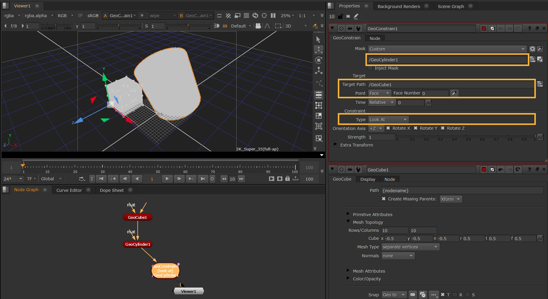
| 5. | Now translating the GeoCube will automatically translate the GeoCylinder to look at the chosen face of the GeoCube. |
Note: The Extra Transform section does as the name implies, allows you to add any additional transformation offsets that you would like, but with the addition of a Coordinate System knob, which lets you specify whether you would like the extra transformers to exist in a Point, Prim, or World coordinate system.
Using the Constrain / Position Tab
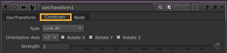
Some other nodes allow you to constrain directly in the node via constraint inputs and the Constrain tab, such as GeoTransform, as well as Axis, Camera, and all of the Light nodes on the Position tab.
This tab works in the same way as the GeoConstrain node, without the need to add an extra node to your node graph. You won't need to select a Mask or a Target, as you will be constraining using the current node and the nodes connected via the constraint input pipe, by default 'look at'. The label on the input pipe will adjust depending on which Constraint Type you select.
An example of using the Look At with Axis, Camera and Lights can be found at Using the Look At Input.