Using USD Lights
There are several USD-native light nodes to choose from in Nuke’s New 3D System. Their node parameters map directly to USD values without any need for conversion. Each light node has a Create and an Edit mode so you can create new lights or edit imported light prims.
To edit imported light prims, you can also use the GeoEditLight node, which combines all four light types specially for editing purposes. You can select the light type under Schema and its options will dynamically populate.
| Light Node | USD Equivalent | Use for: |
| GeoDistantLight | DistantLight | Creating or editing a DistantLight |
| GeoDiskLight |
DiskLight |
Creating or editing a DiskLight |
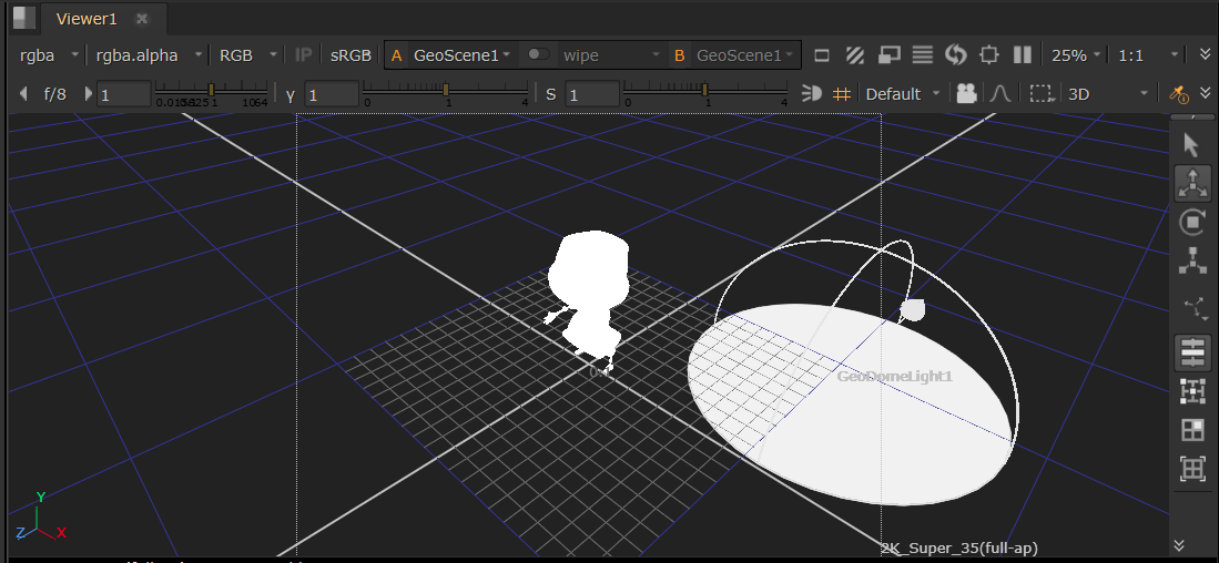
| GeoDomeLight | DomeLight | Creating or editing a DomeLight |
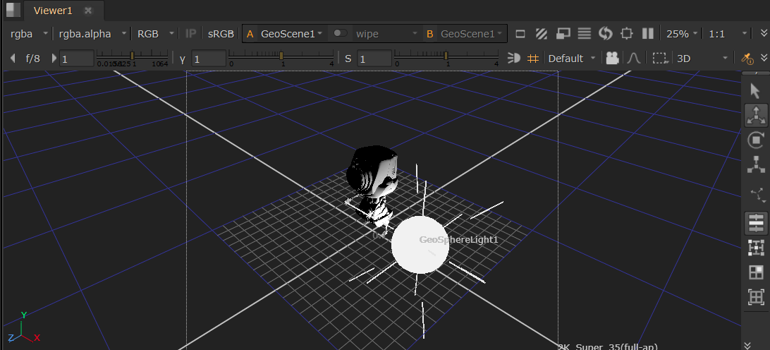
| GeoSphereLight | SphereLight | Creating or editing a SphereLight |
| GeoEditLight | DistantLight, DomeLight, SphereLight, DiskLight | Editing an imported DistantLight, DiskLight, DomeLight, or SphereLight |
Note: See an overview of the different types of lights in Nuke at Light Your Scene.
Adding Lights
To add a light, simply add a light node to your node graph and connect it to the GeoScene node that is downstream of your geometry. In the node properties, under Mode, select either Create or Edit depending on whether you wish to create a new light or edit an existing one.
Creating a Light
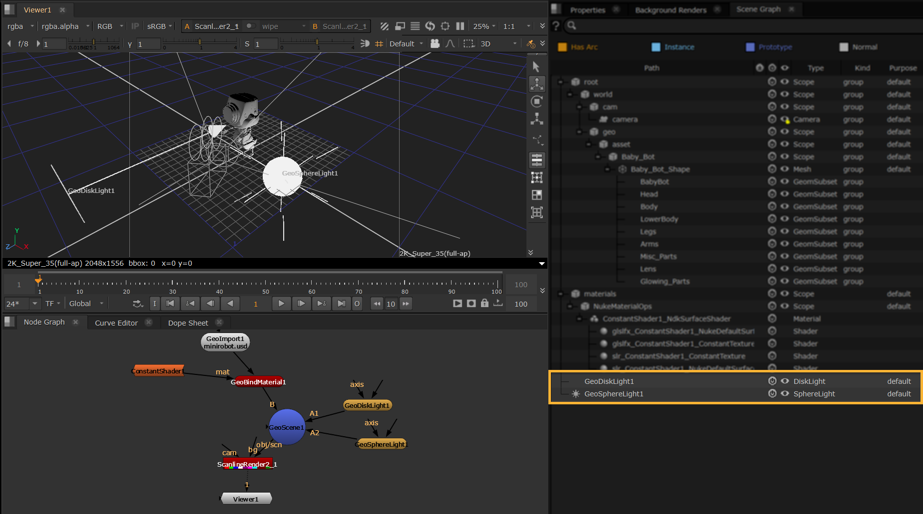
In this example, we are using Create mode, and we have added two of the USD-native light nodes (GeoDiskLight and GeoSphereLight). These appear directly in the Scene Graph as {nodename} - you can change the Path in the light node Properties to adjust this if needed.
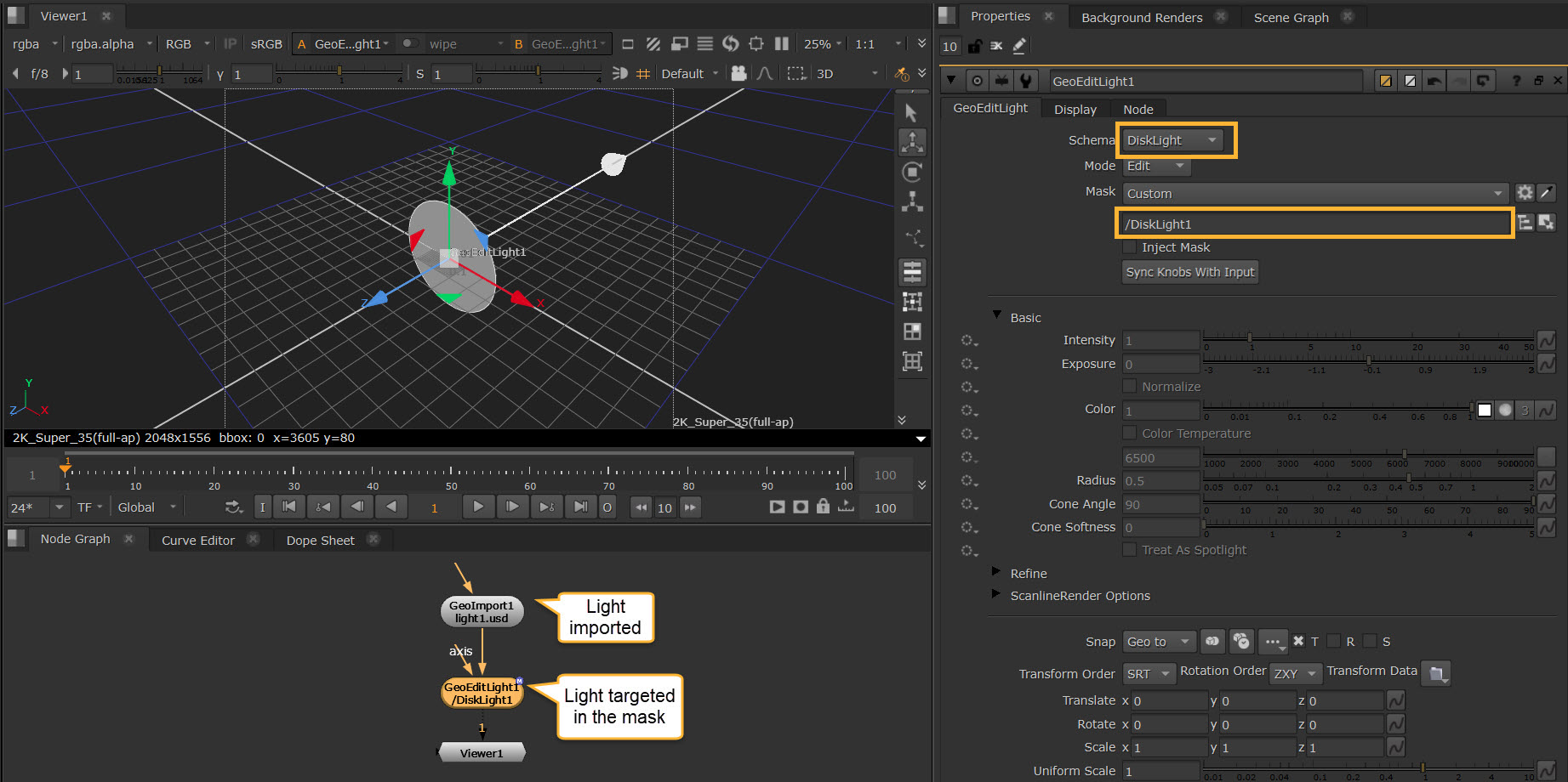
Editing a Light
If you were using Edit mode, you would use the Mask knob to target your existing lights in your scene.
In this example we are using GeoEditLight to target a light from an imported stage by setting the Schema and the Mask.
Note: See Using Paths and Masks to learn more about masking.
Adjusting Light Properties
All lights have Basic, Refine, ScanlineRender Options, Transform, and Display options listed here. Light-specific knobs are outlined in the sections below.
Basic
• You can set the Intensity of the light, which scales the power of the light linearly.
• You can also set an Exposure value which scales the power of the light exponentially as a power of 2, similar to an FStop control.
• You can enable the Normalize checkbox to keep the power of the light constant when the size of the light is altered. This makes it easier to independently adjust the intensity/exposure and size of the light because the total illumination provided will not vary with the area or angular size of the light. May not be respected by all light shader implementations.
• Use the Color wheel to set the color of the light.
• Use the Color Temperature checkbox to enable color temperature. In degrees Kelvin, this represents the white point of the light. When enabled the rgb converted result multiplies against the ‘Color’ control. The default is a common white point 6500k, or D65. Lower values are warmer and higher values are cooler with a valid range from 1000k to 10000k.
Refine
• The Diffuse Amount knob is a multiplier for the effect this light has on diffuse response of materials, so changing this essentially makes a diffuse shader respond differently to the light.
• The Specular Amount knob does the same for the specular response of materials.
ScanlineRender Options
• You can set an Illumination Mask and Receive Shadow Mask if you want the light to cast shadows on other objects. See Lights and Shadows to learn more about the workflow.
Transform
• Each light has the usual transformation options. You can use the transformation handles to transform the lights interactively in the Viewer. See more about how you can use the Viewer at Lights in the Viewer.
Display
• The Display tab allows you to change how the lights look in the Viewer, including locator size and color.
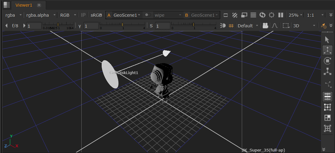
GeoDiskLight
This light node creates a point in 3D space that emits a cone-shaped light.
• The Radius knob controls the radius of the light. A larger radius increases the overall reach of the light.
• The Cone Angle controls the angular diameter of the light in degrees. The light will be cone shaped at smaller angles and behave more like a spotlight.
• The Cone Softness is the softness of the cone angle; typically a value of 1 is used for a soft gradation, while 0 would give the cone angle a hard cut-off. Values greater than 1 can be used to further soften the gradation.
• Focus affects the spread of the light. The greater the value the more focused the light is. Lower values result in a diffused effect.
• Focus Tint changes the color tint of the light in the falloff region determined by the focus property.
• ScanlineRender Options: These changes will not be visible in the 3D viewport via HDStorm as HDStorm doesn’t provide controls for these yet, but will be visible in your ScanlineRender output. Falloff Type controls how much light the object gets from the light source. It is based on the distance between the light source and the object. A Linear type will diminish the light at a fixed rate as it travels from the object. Quadratic and Cubic types will diminish the light at an exponential rate.
Note: All controls are listed in the Node Reference Guide - GeoDiskLight.
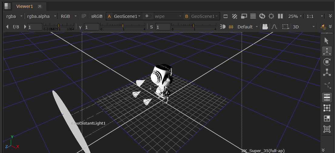
GeoDistantLight
This is a directional light which can be transformed to shine in the direction of your choice in your scene.
• Spread Angle lets you edit the angular diameter of the light in degrees.
• ScanlineRender Options: These changes will not be visible in the 3D viewport via HDStorm as HDStorm doesn’t provide controls for these yet, but will be visible in your ScanlineRender output. Falloff Type controls how much light the object gets from the light source. It is based on the distance between the light source and the object. A Linear type will diminish the light at a fixed rate as it travels from the object. Quadratic and Cubic types will diminish the light at an exponential rate.
Note: All controls are listed in the Node Reference Guide - GeoDistantLight.
GeoDomeLight
This light node can produce a mesh’s specular color, so essentially anything plugged into the map input of the light will show up in the reflections of a mesh.
• Radius is intended to scale the locator in the Viewer. See Lights in the Viewer.
• ScanlineRender Options: These changes will not be visible in the 3D viewport via HDStorm as HDStorm doesn’t provide controls for these yet, but will be visible in your ScanlineRender output. Blur Size allows you to set how much you want to blur the image you are mapping to the light, and Mirror X and Mirror Y will let you flip and flop the image being mapped. You can always opt to create a blur or mirror nodes to do this in the node graph also.
Note: All controls are listed in the Node Reference Guide - GeoDomeLight.
GeoSphereLight
This creates a sphere in 3D space that emits light in every direction.
• The Radius knob controls the radius of the light, where a larger radius increases the overall reach of the light.
• The Treat As Point checkbox essentially reduces the radius to the equivalent size of a point. The Radius knob is greyed out when this Treat As Point is active as you have no need to change the radius in that case.
• ScanlineRender Options: These changes will not be visible in the 3D viewport via HDStorm as HDStorm doesn’t provide controls for these yet, but will be visible in your ScanlineRender output. Falloff Type controls how much light the object gets from the light source. It is based on the distance between the light source and the object. A Linear type will diminish the light at a fixed rate as it travels from the object. Quadratic and Cubic types will diminish the light at an exponential rate.
Note: All controls are listed in the Node Reference Guide - GeoSphereLight.