To edit faces:
| 1. | Activate Edit Mode by selecting |
| 2. | Set the selection mode menu to Select faces |
| 3. | Edit your selection as necessary: |
• To translate, rotate, or scale the selected faces, drag the transform handles that appear on them. To move the pivot point for the transform handles, press Ctrl/Cmd+Alt while dragging on the center of the transformation overlay.
TIP: If necessary, you can also use the controls at the top of the Viewer to set the initial position and alignment of the transform handles (that is, the position used whenever you change the selection). For more information, see Setting the Initial Action Center for Translate, Rotate, and Scale.
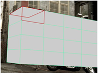
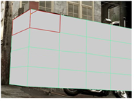
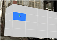
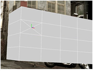
• To carve the selected faces, right-click on them and select carve. A colored border appears around the Viewer window to indicate that the action is in progress. Click on an edge or vertex to begin a carve. All of the surrounding faces are highlighted in red. Click anywhere inside a highlighted face, or on an edge or vertex of a highlighted face, to carve an edge between the previous vertex and the place you just clicked.
|
|
|
| Highlighted faces. | Carving a new edge inside the highlighted faces. |
To carve out a freehand edge, hold down Ctrl/Cmd+Shift and drag.
• To extend your current selection along loops, choose select face loop from the right-click menu. A face loop is a string of connected faces across the model. Often, the last face meets again with the first face, forming a loop.
To create a face loop, you need to select at least two neighboring faces, so that ModelBuilder knows which direction you want to expand the selection in. If the selected faces are above and below each other, ModelBuilder expands the selection vertically. If the selected faces are to the left and right of each other, ModelBuilder expands the selection horizontally. If you have multiple groups of selected faces, they all get expanded out.
|
|
|
| Original selection. | Select face loop. |
Face loops only work with four-sided polygons, known as quads. If a face loop reaches a face with any other number of sides, the loop ends there.
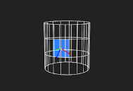
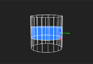
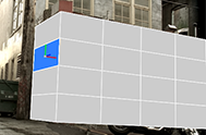
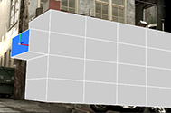
• To extrude the selected faces, select extrude from the right-click menu (or press Return) and drag. This stretches the selected faces into a three-dimensional polygon. ModelBuilder creates faces to complete the object.
|
|
|
| A selected face. | Extruding the selected face. |
If you select extrude from the right-click menu again and extrude the same faces, ModelBuilder creates another three-dimensional polygon next to your first one.
• To merge adjacent faces, select merge from the right-click menu.
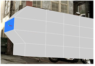
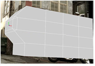
• To bevel the selected faces, select bevel from the right-click menu.
A colored border appears around the Viewer window to indicate that the action is in progress.
At the top of the Viewer, use relative inset to define how far back along the surrounding edges to start the bevel from: 0.0 means no distance and 1.0 means at the opposite end of the edge. The default is 0.1, meaning the beveling starts 1/10th of the way back along each edge.
Set round level to the number of times to repeat the initial bevel, effectively rounding the edges. A value of 0 just does the initial bevel, a value of 1 bevels the output of the initial bevel; a value of 2 bevels the bevel of the initial bevel, and so on.
When you’re happy with the values you’ve entered, press Return to apply the bevel.
|
|
|
| A selected face. | Beveling the selected face. |
Beveling is like extruding the selected faces, except that the resulting polygons have smooth edges and corners. You may want to use beveling to add realism to your model, as real-world objects rarely have perfectly sharp corners.
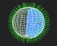
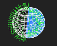
• To invert the selected face's normals, select flip face normals from the right-click menu. This can be useful, for example, if editing operations (such as a sequence of extrusions) have resulted in normals that point the wrong way.
TIP: To see the normals, press S on the Viewer to display the Viewer Settings, go to the 3D tab, and activate the show primitive normals button ![]() .
.
|
|
| Before flip face normals. | After flip face normals. |
• To turn the selected face into a triangle fan, select tessellate > triangle fan from the right-click menu. This adds a new vertex at the center of the face and joins each of the vertices around the perimeter of the face to it. It can be useful if you want to quickly add more detail to your mesh.
|
|
|
| A selected face. | The same face with a tessellated triangle fan. |
• To delete the selected faces, select delete faces from the right-click menu (or press Delete).