To edit vertices:
| 1. | Activate Edit Mode by selecting |
| 2. | Set the selection mode menu to Select vertices |
| 3. | Edit your selection as necessary: |
• To translate, rotate, or scale the selected vertices, drag the transform handles that appear on them. To move the pivot point for the transform handles, press Ctrl/Cmd+Alt while dragging on the center of the transformation overlay.
TIP: If necessary, you can also use the controls at the top of the Viewer to set the initial position and alignment of the transform handles (that is, the position used whenever you change the selection). For more information, see Setting the Initial Action Center for Translate, Rotate, and Scale.
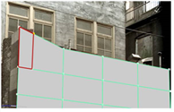
• To carve the selected vertices, right-click on them and select carve. A colored border appears around the Viewer window to indicate that the action is in progress. Click on an edge or vertex to begin a carve. All of the surrounding faces are highlighted in red. Click anywhere inside a highlighted face, or on an edge or vertex of a highlighted face, to carve an edge between the previous vertex and the place you just clicked.
|
|
|
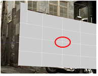
| A highlighted face. | A new edge carved inside the highlighted face. |
To carve out a freehand edge, hold down Ctrl/Cmd+Shift and drag.
• To extrude the selected vertices, select extrude from the right-click menu and drag. This stretches the selected vertices into three-dimensional polygons. ModelBuilder creates faces to complete the object, for example a rectangular pyramid from a vertex.
|
|
|
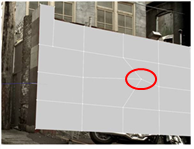
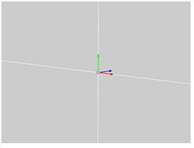
| A selected vertex. | Extruding the selected vertex. |
• To bevel the selected vertices, select bevel from the right-click menu.
A colored border appears around the Viewer window to indicate that the action is in progress.
At the top of the Viewer, use relative inset to define how far back along the surrounding edges to start the bevel from: 0.0 means no distance and 1.0 means at the opposite end of the edge. The default is 0.1, meaning the beveling starts 1/10th of the way back along each edge.
Set round level to the number of times to repeat the initial bevel, effectively rounding the edges. A value of 0 just does the initial bevel, a value of 1 bevels the output of the initial bevel; a value of 2 bevels the bevel of the initial bevel, and so on.
When you’re happy with the values you’ve entered, press Return to apply the bevel.
|
|
|
| A selected vertex. | Beveling the selected vertex. |
Beveling is like extruding the selected vertices, except that the resulting polygons have smooth edges and corners. You may want to use beveling to add realism to your model, as real-world objects rarely have perfectly sharp corners.
• To delete the selected vertices, select delete vertices from the right-click menu (or press Delete).
Note that you can only delete simple vertices that have no more than two edges connected to them.