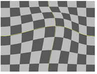
The GridWarp node allows you to warp images by transferring image information from one Bezier grid onto another. When using this node, you first position the source grid, which defines where to warp from. Next, you position the destination grid, which defines where to warp the image to. This grid can be a duplicate of the source grid, or you can define it separately. When you manipulate the destination grid, the corresponding warp is applied to the source image.
The GridWarp node also includes controls for animating the warp and selecting the level of filtering used to remove any artifacts the warp may have caused.
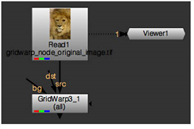
| 1. | Select Transform > GridWarp to insert a GridWarp node after the image you want to warp. |
| 2. | Connect the src input and a Viewer to the image. |
| 3. | When the GridWarp properties panel is open, by default the destination grid overlay appears in the Viewer. You can show or hide the source and destination grids using the |
NOTE: GridWarp automatically attempts to resize the grids to the image size as long as you have not modified any of the control points.
If the grids are not the same size as the input image, click the Resize to image buttons under both Source Grid and Destination Grid.
| 4. | Use the Viewer tools to control the following aspects of the grids: |
NOTE: You can use the copy and paste buttons ![]() in the grid controls to copy control point keyframes between the source and destination grids.
in the grid controls to copy control point keyframes between the source and destination grids.
|
Control |
What it does |
|
output |
Controls the output displayed in the Viewer: • source - the source image and source grid. • source warped - the source image and destination grid. • destination - the destination image and destination grid. • destination warped - the destination image and source grid. • morph - the morphed image, controlled by the warp and mix parameters, and both grids. |
|
|
When enabled, the grids shown in the Viewer depends on the output setting. For example, if output is set to source warped, only the destination grid appears in the Viewer. |
|
|
When enabled, the source grid is displayed in the Viewer. This control can be overridden by the |
|
|
When enabled, the destination grid is displayed in the Viewer. This control can be overridden by the |
|
|
When enabled, changes to points in a grid are automatically keyed. You can disable this and set your keyframes manually, which is particularly useful if you intend to use the Curve Editor. See Animating Warps. |
|
ripple |
Rippling keyframes allows you to adjust the position of a stroke/shape point on one frame and have that same relative adjustment applied to the point across all frames or a specified range of frames. • off - ripple edit is disabled. • all - ripple all frames in the sequence. • from start - ripple frames from the first frame to the current frame. • to end - ripple frames from current frame to the last frame. • range - ripple all frames within the from and to fields. |
|
label points |
When enabled, points selected on the grid are labeled x,y measured from the origin. |
|
|
When enabled, the transform handle overlays all selected points. |
|
|
When enabled, a low resolution preview displays when points are moved on a grid. Once the render is complete, the low-res image is updated. |
|
divisions |
Enter the number of divisions required in the field to modify the grid. The number of divisions must be between 3 and 20. You can also click and hold the slider to overlay a preview of the subdivisions. GridWarp attempts to modify the grid based on the current control point distribution. NOTE: When using the preview, accuracy may suffer at lower divisions and additional smoothing may be required at higher divisions. |
|
|
Click to enable Edit mode. Select individual points, multiple points using shift-click, or marquee groups of points. Edit mode also allows you to adjust the curve between points to produce distortion. |
|
|
Click to enable Insert mode. Click on a horizontal line to add a vertical line to the grid and vice versa. |
|
|
Click to enable Delete mode. Click on a grid line to remove it from the Viewer. |
|
|
Click to enable Draw Boundary mode. The cursor changes to a crosshair and you can drag a marquee in the Viewer to create a custom grid. |
|
|
Click to subdivide the grid columns across the currently selected area. |
|
|
Click to subdivide the grid rows across the currently selected area. |
|
|
Click to subdivide the grid columns and rows across the currently selected area. |
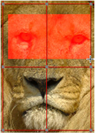
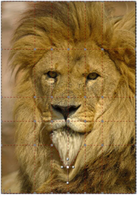
| 5. | Modify the grid around the area you want to warp. Usually, you want the grid to conform to the subject of the source image. For example, if you are warping an animal’s eyes, you need to create grid lines that follow the edges of the eyes. |
NOTE: If you have both grids visible when you move a point, and the same point for both grids are on top of each other, both points are moved and you won’t see any distortion.
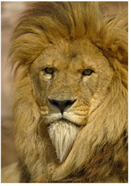
You can use the grid lines to isolate the areas you do not want to warp. You do this by adding grid lines between the area you intend to warp and the area you don’t want to change.
|
|
|
| An unlimited warp. | The same warp limited to a small area with grid lines. |
When you select a point, four tangent handles appear around it. You can use these handles to modify the curves connecting the points.

To move several points together, draw a marquee around them and use the transformation overlay that appears.
![]()
You can also use the Draw Boundary tool in the Viewer to quickly set a user defined grid. Click Draw Boundary and draw a marquee over the required area of the image.
|
|
|
| The Draw Boundary marquee. | The resulting user-defined grid. |
NOTE: You can also use the Curve Editor to edit curves by right-clicking a control point and selecting Curve Editor > points, tangents, or both.
The curves appear in the Dope Sheet as long as the GridWarp Properties panel is open.
| 6. | In the areas where you want to warp the image, drag the points on the grid to a new position. When you click on a point, the point changes color to indicate whether it’s in focus (green by default) and whether it has an expression set (red by default). You can change the default colors on the Viewers tab in the Preferences. |
The pixels in these areas are moved in the direction you moved the points. Pixels in the nearby areas are also moved to accommodate the change, but the distortion lessens the further you get from the repositioned points. If you don’t want a nearby area distorted, add more grid lines between the area and the points you want to move before you drag the points to a new location.
TIP: You can nudge selected control points by a single pixel using the numeric pad 4 and 6 to nudge left and right, or 8 and 2 to nudge up and down.
Holding down Shift and using the numeric pad moves the selected points by 10 pixels, for example, Shift+6 moves the selected points 10 pixels to the right.
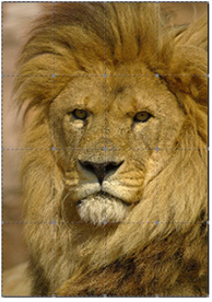
| 7. | To better see what the warped image looks like, press O on the Viewer to toggle the overlay off. |
To compare the original and warped images, press D on the GridWarp node to disable and enable it. If you see changes in the areas you don’t want to warp, go back to modifying the grid.
| 8. | If necessary, animate the grid to match any movement in the source image. For more information on how to do this, see Animating Warps. |
| 9. | You can adjust the controls described in the following table to enhance your results. |
|
Control |
What it does |
|
GridWarp Tab |
|
|
channel |
Sets the channels affected by the distortion. |
|
mask |
Connect a mask input and set the channel to use as a mask. By default, the mask is limited to the non-black areas of this channel. Use the checkboxes to modify the mask properties: • inject - copies the mask input to the predefined mask.a channel. Injecting the mask allows you to use the same mask further downstream. • invert - inverts the use of the mask channel so that the mask is limited to the non-white areas of the mask. • fringe - blurs the edges of the mask. |
|
background |
The warped image is rendered on top of an unwarped background. This control sets what to use as that background: • on black - render the warped image on top of a constant black image. • on src - render the warped image on top of the image connected to the src input of the GridWarp node. • on dst - render the warped image on top of the image connected to the dst input of the GridWarp node. • on bg - render the warped image on top of a background image connected to the bg input of the GridWarp node. |
|
background mix |
Blends between the output of the GridWarp node (at 0) and whatever you have selected from the background dropdown menu (at 1). |
|
Set bbox to |
Sets the boundary box properties. |
|
Render Tab |
|
|
submesh |
Sets the number of subdivisions that are created between Bezier curves in the grid. The higher the value, the more accurate the distortion between the grid lines, but rendering time increases. |
|
filter |
Select the appropriate filtering algorithm (see Choosing a Filtering Algorithm). |
|
Options Tab |
|
|
source color |
Sets the source grid color. |
|
destination color |
Sets the destination grid color. |