The SplineWarp node deforms an image based on multiple Bezier or B-spline curves that you create. Source curves define where to warp from, while destination curves define where to warp the source image to. Unlike the GridWarp node, you can draw these curves anywhere on the image, rather than only adding points on the existing grid lines, then join them to create the source and destination. The controls for adding and modifying points are similar to the RotoPaint node controls.
| 1. | Select Transform > SplineWarp to insert a SplineWarp node after the image you want to warp. |
| 2. | Connect the A input to the image and attach a Viewer to the SplineWarp node. |
| 3. | Use the Viewer tools to control the following: |
|
Control |
Name |
What it does |
|
|
autokey |
When enabled, changes to points and shapes are automatically keyed. You can disable this and set your keyframes manually, which is particularly useful if you intend to use the Curve Editor. See Animating Warps for more information. |
|
|
label points |
When enabled, points selected in the Viewer are numbered sequentially. |
|
|
hide curves |
When enabled, curve lines are hidden. |
|
|
hide points |
When enabled, points are hidden. |
|
|
hide transform handle |
When enabled, the transform handle is hidden when a selection is made. |
|
|
hide transform handle when moved |
When enabled, the transform handle is hidden when a selection is moved. |
|
|
constant selection |
When enabled, clicking in the Viewer does not deselect the current shape(s). |
|
|
ripple |
Rippling keyframes allows you to adjust the position of a stroke/shape point on one frame and have that same relative adjustment applied to the point across all frames or a specified range of frames. • all - ripple all frames in the sequence. • from start - ripple frames from the first frame to the current frame. • to end - ripple frames from current frame to the last frame. • range - ripple all frames within the from and to fields. |
|
|
add/remove |
Add and remove keyframes at the current playhead position using these buttons. |
|
|
output A |
When enabled, output the image attached to the A input and any shapes in the curves list labeled with A. |
|
|
output A warped |
When enabled, output the image attached to the A input warped by any shapes in the curves list labeled with A. |
|
|
output AB morph |
When enabled, output the morphed A and B inputs and any shapes in the curves list labeled with AB. |
|
|
output B |
When enabled, output the image attached to the B input and any shapes in the curves list labeled with B. |
|
|
output B warped |
When enabled, output the image attached to the B input warped by any shapes in the curves list labeled with B. |
|
|
show source curves |
When enabled, joined source curves are displayed in the Viewer. |
|
|
show destination curves |
When enabled, joined destination curves are displayed in the Viewer. |
|
|
show correspondence points |
When enabled, all correspondence points are displayed in the Viewer when a Correspondence tool is selected. |
|
|
show boundaries |
When enabled, all boundary curves are displayed in the Viewer. |
|
|
show hard |
When enabled, all hard boundary curves are displayed in the Viewer. NOTE: Hard boundary is only useful on closed curves. |
|
|
visibility |
Controls visibility for the selected shape. |
|
|
lock |
Controls the lock state of the selected shape. Locked shapes cannot be modified. |
|
|
toggle boundary |
Toggles the Boundary state of the selected shape(s). Clicking toggle boundary on a standard shape defines it as a Boundary and vice versa. See Using Boundary Shapes and Pins to Limit Warp for more information. |
|
|
update mode |
Sets the Viewer update mode: • off - no updates are applied when points are moved. Use this option for complex warps where the Viewer update can be slow. • on - the Viewer updates in real-time to help you position points. With complex scripts, this mode maybe prohibitively slow. • persistent - similar to on, but displays a preview until the render is complete, rather than showing real-time scanlines. |
|
|
Select tool |
Click to enable Select mode allowing you to select points and shapes, or marquee select multiple points and shapes. |
|
|
Points tool |
Click to enable Add mode or toggle between Add, Remove, Cusp, Smooth, Open/Close, and Remove Destination modes. Click on existing shapes to add or modify points. |
|
|
Draw tool |
Click to enable Draw mode or toggle between Bezier, Cusped Bezier, B-spline, Ellipse, Rectangle, and Cusped Rectangle mode. Click on the Viewer to draw the selected shape. |
|
|
Correspondence tool |
Click to enable Correspondence mode or toggle between Add, Modify, and Remove mode: • Add - clicking on a joined curve creates a correspondence point. These points are used to improve the warp accuracy in isolated areas, but overuse can cause performance issues. • Modify - allows you to move an existing correspondence point along its curve, in either direction, as far as the next point on the shape. • Remove - click to remove an existing correspondence point. |
|
|
Pin tool |
Click to enable Pin mode. You can use pins as single point joined curves to create warp or to secure specific points in place to isolate them from warping. |
|
|
Join tool |
Click to enable Join mode or toggle between Join, Reverse, and Unjoin mode. |
| 4. | Click |
| 5. | Select the Draw tool |
NOTE: If you’re creating multiple open splines, draw your first spline and then press Esc or select another tool to let SplineWarp know you’re done. Reselect Draw to begin drawing another spline.
| 6. | You can modify shapes by adding points using the Add tool and adjusting the tangent handles that appear around it. |
When you mouse over a point, it turns green. Clicking on a point changes its color to indicate it’s selected (white by default) and whether it has an expression set (red by default). You can change the default colors on the Viewers tab in the Preferences.
To move several points together, draw a marquee around them and use the transformation overlay that appears.
![]()
To close an open curve or open a closed curve, right-click on a point and select open/close curve.
To remove a point, right-click on the point and select delete.
NOTE: You can also use the Curve Editor to edit curves by right-clicking a control point and selecting curve editor > points or points+tangents.
The curves appear in the Dope Sheet as long as the SplineWarp Properties panel is open.
| 7. | Once you’re happy with the source curve, either: |
• draw a destination curve and use the Join ![]() tool to connect the two curves.
tool to connect the two curves.
OR
• right-click a point on the source curve and select duplicate in A and join to produce the destination curve.
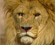
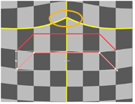
| 8. | Select the destination curve and drag points or the entire shape to a new position. The pixels in these areas are warped in the direction of movement. |
|
|
|
| The image A and warp curves. | The warped image. |
| 9. | To better see what the warped image looks like, press O on the Viewer to toggle the overlay off. |
To compare the original and warped images, press D on the SplineWarp node to disable and enable it. If you see changes in the areas you don’t want to warp, go back to modifying your shapes.
| 10. | Using the curves list, you can quickly build up a complex warp hierarchy using the add/remove |
Using the root, layer, and pair warp controls, you can affect different elements as required:
• root warp - affects warp globally, irrespective of layer and pairing.
• layer warp - affects warp on the selected layers only, irrespective of pairing. This control is disabled if anything other than layers is selected.
• pair warp - affects warp on the selected pairings only. This control is disabled if anything other than pairs is selected.
NOTE: The pair warp value is multiplied by the layer warp value, which is in turn multiplied by the root warp value.
| 11. | If necessary, animate the source warped shapes to match any movement in the source image. For more information on how to do this, see Animating Warps. |
| 12. | You can adjust the controls described in the following table to enhance your results. |
|
Control |
What it does |
|
SplineWarp tab |
|
|
crop to format |
When disabled, the input image is not cropped to the Project Settings > full format size. As a result, warping can introduce pixels from the image outside the format size, rather than black. NOTE: Disabling crop to format can affect performance as Nuke has to calculate the warp for the entire image, not just the area inside the format size. |
|
bbox boundary curve |
When enabled, a boundary curve is added around the input format, limiting warp at the edges of the image. NOTE: In AB morph mode, the format of input A is taken as the boundary. |
|
Render Tab |
|
|
curve resolution |
Adjusts the accuracy of the warp/spline match. Higher values increase accuracy, but sacrifice speed and vice versa. For example, with open splines at low curve resolution, image tearing may occur. You can raise the curve resolution value to compensate for tearing, but the render times increase. NOTE: Correspondence points may be used to improve the warping accuracy in a specific part of the curve if turning this value up too high causes performance problems. |
|
boundary curve resolution |
Adjusts the number of interpolated points on boundary and hard boundary curves. Higher values stop the warp from filtering through the boundary curves but sacrifice speed, and vice versa. |
|
preview resolution |
Improves the accuracy of the preview at higher values and the rendering speed at lower values. |
|
Classic warping |
Set the type of warp function to use: • disabled - uses an updated quadratic warp function that copes well with overlapping control points, but has a more local warp effect. • enabled - employs a warping function from previous versions of Nuke that has a more global warp effect, but doesn’t cope well with overlapping control points. |
|
filter |
Select the appropriate filtering algorithm (see Choosing a Filtering Algorithm). |
You may notice that pixels in areas around warping are also moved to accommodate the change, but the distortion lessens the further you get from the repositioned points. If you don’t want a nearby area distorted, you can:
• Designate a curve or shape as a boundary to control or eliminate warp.
• Place pins in the areas you want to limit warp.
NOTE: Boundaries only affect the input they are drawn on, A or B, not both.
• Boundary - generally open splines helping to control warp rather than eliminate it.
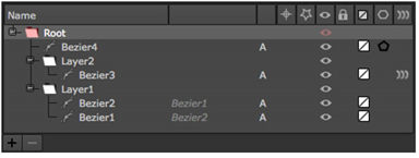
To define a boundary for an existing curve, enable boundary in the curves list, as shown below.

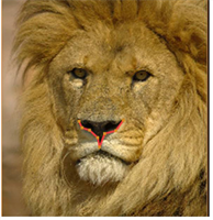
Using the example curves from Mr. Lion above, you could control the warp by adding a curve and designating it as a boundary:
|
|
|
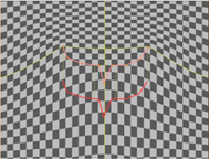
| The source and destination curves. |
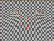
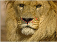
The same curves, but with a boundary above the destination to limit warp. |
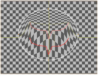
• Hard Boundary - closed shapes that eliminate warp outside the area that they enclose.
To define a hard boundary for an existing shape, enable hard boundary in the curves list, as shown below.

The effect of a hard boundary on a warp is quite distinct - the hard boundary, colored white by default, limits the warp effect to entirely within the closed shape:
|
|
|
• Pins - placing a pin creates a single point source and destination curve, effectively limiting warp in a very localized way.
The effect of a pin on a single joined curve is shown below. The warp direction is shown on the left and the pin’s effect on the right.
|
|
|