Matching and Solving Warps
C_GlobalWarp uses feature detection, similar to that employed by C_CameraSolver, to locate features in the overlap regions of adjacent camera pairs. The warp then uses these features to find the best-fit gridwarp deformation of each input view to reduce ghosting.
To warp a sequence:
| 1. | Connect a C_GlobalWarp node to the output of your C_CameraSolver node. |
| 2. | CaraVR automatically adds a single keyframe at the current frame, but you can add keyframes manually by either: |
• scrubbing in the Viewer and then clicking Add Key (![]() ) to add a keyframe at the current frame, or
) to add a keyframe at the current frame, or
• clicking Key All to add keyframes throughout the sequence at the Step interval.
If you have a lot of movement in your sequence, set the Step interval to a lower value so that the greater difference between frames is accounted for in the stitch. The opposite is true for more static sequences, where a higher value may produce better results.
• clicking Import and selecting the node from which you want to import keyframes. You can import keyframes from any instance of C_CameraSolver, C_Stitcher, C_GlobalWarp, or C_ColourMatcher in the script.
Any matches in C_CameraSolver are also imported by default. If you don't need matches from the solver, disable Import available matches.
Note: C_Stitcher only computes optical flow camera warps at designated keyframes, it ignores upstream animation that does not fall on the same keyframes. Use the Import button to copy over all keyframes from C_CameraSolver. This way, any additional per-camera, manual keyframes added in the Cameras tab are also copied.
Adding keyframes manually can help in blurred areas between existing keyframes where the interpolation is inaccurate.
The more keyframes you add, the longer the process takes, though you may get better results. The global warper blends the input images to create the final warped frames.
| 3. | Click Match to compare keyframes on overlapping cameras for shared features. CaraVR only looks for matches in cameras that overlap by default. |
Note: Match calculates the feature matches for all cameras in the rig at the same time, so there is no need to calculate them separately for left and right images in a stereo setup. See Stitching Stereographic Rigs for more information.
| 4. | Click the Camera Matches |
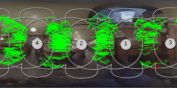
Camera matches represent a single feature in both views, and the estimated warp destination of the feature. For example, the image shows a smoke detector in views 2 and 4 and the warp destination point in between.
|
|
|
|
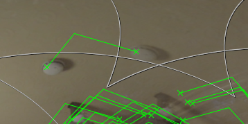
Pre-warp matches. |
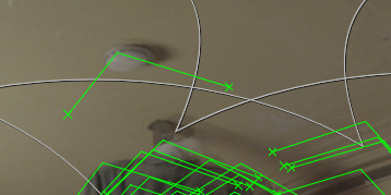
Warp destination. |
| 5. | Click Warp to calculate the warp. |
Note: The warp is calculated for all cameras in the rig at the same time, so there is no need to calculate them separately for left and right images in a stereo setup. See Stitching Stereographic Rigs for more information.
The warped preview image displays in the Viewer. See Troubleshooting Matches and Warps for information on improving warp results.
When you're satisfied with the initial global warp, you can add constraints to reduce warping on known straight lines in the rectilinear input images. See Constraining Warps for more information.