Drawing Grids
The From and To grids control the area and extent of the warp or morph, so drawing accurate grids around the feature you intend to warp can improve the result. You can link the From and To grid before drawing your grid or copy points between grids using the copy ![]() and paste
and paste ![]() buttons.
buttons.
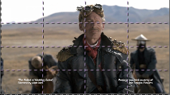
The grids covers the entire input image by default, but in most cases you'll want to confine the warp to an area of interest in the image.
|
|
|
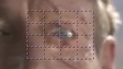
| 1. | Enable the Draw Boundary |
Tip: If you want to see your grid in the context of the whole image, set the Background control to Src, otherwise the rest of the image is masked out.
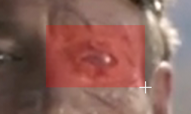
| 2. | You can then use the Insert |
Tip: If you prefer, you can use the subdivide buttons ![]()
![]()
![]() to quickly add columns and rows to multiple selections.
to quickly add columns and rows to multiple selections.
| 3. | Link the From and To grids before adjusting the points by clicking the link |
If you want to keep the grids separate for now, you can always copy the keyframes from one to the other using the ![]() and paste
and paste ![]() buttons.
buttons.
| 4. | Enable the Edit |
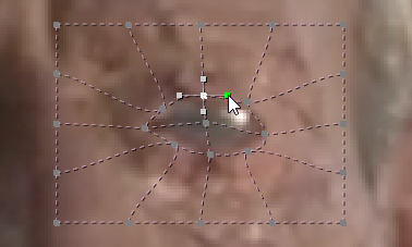
Generally, more accurate grids produce better results, so it's worth taking some time to match the grid to the feature you're warping.
| 5. | You can control how points appear in the Viewer using the label and overlay buttons: |
•
![]() - enable to display a transform handle overlay on all selected points, allowing you to transform them all at once.
- enable to display a transform handle overlay on all selected points, allowing you to transform them all at once.
•
![]() - enable to display x,y labels on points selected in the grid.
- enable to display x,y labels on points selected in the grid.
•
![]() - enable to display the grid a point belongs to, its color, and locked state when you hover over it.
- enable to display the grid a point belongs to, its color, and locked state when you hover over it.
| 6. | Proceed to Tracking Using the Tracker Node if you don't have access to NukeX or Nuke Studio's SmartVector node, |
OR
Tracking Using SmartVectors if you do have SmartVector data.
Note: SmartVector data can be written out to .exr files and used in vanilla Nuke, you don't have to calculate the vectors in context. See Generating Motion Vectors for more information.