ParticleVortex
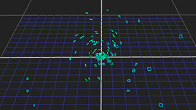
ParticleVortex applies a circular force to the particles and attracts them to an imaginary line, thus creating a whirlpool of particles. When you connect the ParticleVortex node to your particle stream, an arrow appears in the 3D Viewer, which you can then use to determine direction and velocity of the vortex effect. The bigger and longer the arrow, the stronger the effect.
Inputs and Controls
|
Connection Type |
Connection Name |
Function |
|
Input |
particles |
The particle system to which you intend to apply the vortex. |
|
Control (UI) |
Knob (Scripting) |
Default Value |
Function |
|
ParticleVortex Tab |
|||
|
display |
display |
unchanged |
Adjust the display characteristics of the particles. These settings don’t affect the render output of the scene; these are for display purposes only in the 3D Viewer. • off - hides the particles. • wireframe - displays only the outlines of the particle. • solid - displays all particles with a solid color. • solid+wireframe - displays the particles as solid color with the particles outlines. • textured - displays only the surface texture. • textured+wireframe - displays the wireframe plus the surface texture. • unchanged - doesn't change the particles display mode. The Viewer can override this setting. |
|
selectable |
selectable |
enabled |
When enabled, you can select the particles in the Viewer by clicking on them. |
|
render |
render_mode |
unchanged |
Sets how the particles will render. This control is independent from the display selection, but has the same settings. |
|
parallel |
parallel |
0 |
Applies a force to particles in a direction parallel to the vector line. Negative values flow with the vector line and positive values against it. |
|
parallel falloff |
parallel_falloff |
none |
Sets which falloff law to use when calculating the effect of the force on each particle: • none - no falloff occurs, regardless of distance from the origin. • inverse and inverse square - falloff is calculated with respect to the selected law. |
|
tangential |
tangential |
0 |
Applies a force to particles in a direction tangential to the vector line. Negative values produce clockwise movement around the vector line and positive values counter-clockwise. |
|
tangential falloff |
tangential_falloff |
inverse |
Sets which falloff law to use when calculating the effect of the force on each particle: • none - no falloff occurs regardless of distance from the origin. • inverse and inverse square - falloff is calculated with respect to the selected law. |
|
radial |
radial |
0 |
Applies a force which attracts particles to (positive values), or repels them from (negative values) the vector line. |
|
radial falloff |
radial_falloff |
inverse |
Sets which falloff law to use when calculating the effect of the force on each particle: • none - no falloff occurs regardless of distance from the origin. • inverse and inverse square - falloff is calculated with respect to the selected law. |
|
from xyz |
from |
0, 0, 0 |
Sets the point of origin for the arrow on the x, y, and z axes. The arrow determines the direction and velocity of the vortex effect. The bigger and longer the arrow, the stronger the effect. |
|
to xyz |
to |
0, 1, 0 |
Sets the point of destination for the arrow on the x, y, and z axes. The arrow determines the direction and velocity of the vortex effect. The bigger and longer the arrow, the stronger the effect. |
|
Conditions Tab |
|||
|
probability |
probability |
1 |
Sets the probability that this node affects your particles. If you set this to zero, the node won’t affect any particles, and if the value is 1, the node will affect every particle. |
|
min age |
min_age |
0 |
Limits the effect of this node to particles above this minimum age. The age of the particle is its lifetime normalized between 0 and 1. |
|
max age |
max_age |
1 |
Limits the effect of this node to particles below this maximum age. The age of the particle is its lifetime normalized between 0 and 1. |
|
random seed |
seed |
0 |
Sets the integer to change the results of generated randomness in your particles. You can achieve slightly different effects by changing this number. |
|
channels |
channels |
all |
Specifies which particle channels the effect of this node should be applied to. Channels a and b are arbitrary names for channels which are useful if you want different ParticleEmitter nodes or other particle force nodes to have an effect on separate channels. |
|
Region Tab |
|||
|
region |
region |
none |
Sets the region which you want to use to confine the particle effect to. For example, if you choose a sphere, only particles inside that sphere shaped region will be affected by particle effects. • none - all particles are affected as normal. • sphere, box, half-space, and cylinder - controls the region’s boundary shape. |
|
invert region |
region_invert |
disabled |
When enabled, particles outside the region are affected rather than those inside it. |
|
|
file_menu |
N/A |
Select to import or export a channel file: • Import chan file - import a channel file and transform the region marker according to the transformation data in the channel file. Channel files contain a set of Cartesian coordinates for every frame of animation in a given shot. You can create and export them using Nuke or 3D tracking software, such as 3D-Equalizer, Maya, or Boujou. • Export chan file - export the translation parameters that you’ve applied to the region marker as a channel file. This is a useful method of sharing setups between artists. |
|
|
snap_menu |
N/A |
• Match selection position - the region marker is snapped to a new position depending on the points selected. • Match selection position, orientation - the region marker is snapped to a new position and orientation depending on the points selected. • Match selection position, orientation, size - the region marker is snapped to a new position, orientation, and size depending on the points selected. |
|
transform order |
xform_order |
SRT |
Sets the operation order for scale (S), rotation (R), and translation (T). The possible operation combinations are SRT, STR, RST, RTS, TSR, TRS. |
|
rotation order |
rot_order |
ZXY |
Sets the order of rotation. The possible axial combinations are ZXY, XYZ, XZY, YXZ, YZX, ZXY, ZYX. |
|
translate |
translate |
0, 0, 0 |
Lets you translate the region marker along the x, y, and z axes. You can also adjust translate values by clicking and dragging the axis in the 3D Viewer. |
|
rotate |
rotate |
0, 0, 0 |
Lets you rotate the region marker around the x, y, and z axes. You can adjust rotate values by holding down Ctrl/Cmd and dragging in the 3D Viewer. |
|
scale |
scaling |
1, 1, 1 |
Lets you scale the region marker on the x, y, and z axes. |
|
uniform scale |
uniform_scale |
1 |
Lets you scale the region marker simultaneously on the x, y, and z axes. |
|
skew |
skew |
0, 0, 0 |
Lets you skew the region marker on the x, y, and z axes. |
|
pivot |
pivot |
0, 0, 0 |
When you make changes to the region marker’s position, scaling, skewing, and rotation, these occur from the location of the object’s origin point or pivot. The pivot x, y, and z controls allow you to offset the pivot point and move it anywhere you like - you can even move it outside of the object. Subsequent transformations applied will then occur relative to the new pivot point location. You can also hold down Ctrl/Cmd+Alt and drag the pivot point to a new location in the 3D Viewer. |
|
Local Matrix |
|||
|
specify matrix |
useMatrix |
N/A |
Enable this control to specify matrix values for the object you’re transforming as an alternative to setting transform, scale, skew and pivot values above. |
|
matrix |
matrix |
N/A |
The matrix displays values from the object’s transform, rotate, scale, skew, and pivot controls. Check specify matrix and copy or drag-and-drop matrix values from another object to apply those values, for example, if you wanted to align objects in a scene. |

Step-by-Step Guides
Adding Spiral Motion to Particles
Example Nuke Scripts
Creating a whirlpool of particles