Basic Concepts
Nuke new 3D system differs from the classic one in several fundamental aspects and there are a number of concepts that are quite different. We’ve tried to keep things familiar where possible, but the different nature of USD means that some things will change, exposing new workflow opportunities and requiring some adjustment to how we approach 3D workflows in Nuke.
The Stage
In earlier Nuke releases, geometry data passes through the node graph as a flat
list of objects. In Nuke 14.0 though, the data that is passed through the 3D
node graph is a USD stage. You can think of each node in Nuke 14.0 as accepting
a stage, making changes to it and outputting the modified stage. A stage can be
imported from a USD file with the GeoImport node, modified with other nodes
such as GeoTransform and then displayed in the Hydra-based viewer. The 3D stays
as a USD stage throughout and there is no conversion to other data formats and
hence the process is completely lossless. Compare this to the classic 3D
system: ReadGeo converts the USD to Nuke’s internal representation which
flattens the scene graph hierarchy and necessarily involves loss of attribute
data not supported by Nuke. The conversion process also takes time and memory,
so the USD system performs better for large scenes.
The Scene Graph
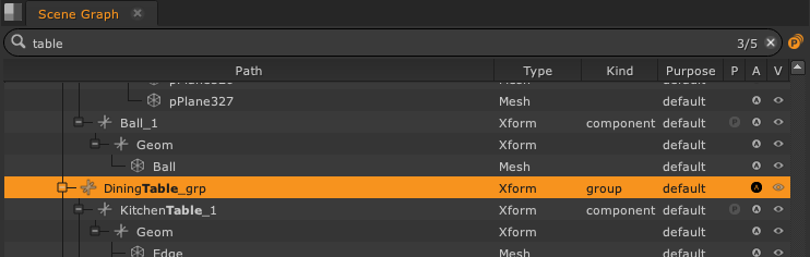
The feature of USD that has the biggest impact on how Nuke works is the hierarchical scene graph of the USD stage. Nuke’s new scene graph offers an overview of the stage, and is essentially a list of everything within the 3D stage at the point where the Viewer is connected. It is a tool to view, navigate and manage large 3D scenes, making it easier to work with larger and more complex 3D scenes, focusing on efficiency, and familiarity with other software packages.
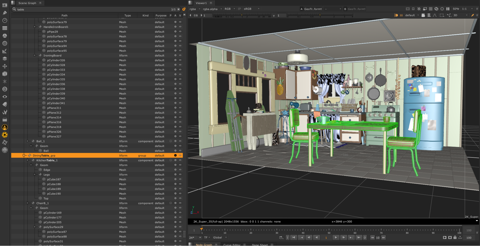
With this in mind, we have introduced a new dedicated panel in the 3D workspace and included functionality such as visibility toggles, search functionality, geometry highlight synchronisation, hotkeys and payloads.
The scene graph comes hand-in-hand with the new hierarchical structure of the USD stage. In Nuke’s classic 3D system, geometry had a fixed structure consisting of a flat list of objects, each of which had a transform and a number of geometric primitives. The new stage has a full hierarchical structure which is much more flexible, but this has a number of consequences which force nodes to work in a different way.
The first difference is that all objects in the stage have a unique path such
as: /Island/Forest/Trees/Tree1/Branch3/Leaf5768. In Nuke 14.0, the paths are
used to define where nodes create objects and which objects they should work
on. In past Nuke versions, there was no structure, so the only way to uniquely
identify geometry was by its position in the list or by naming the node which
created it. Using the position is fragile as it can easily change, and using
the node name doesn’t distinguish between multiple objects produced by the same
node (e.g. a ReadGeo). This means that Nuke was good at handling workflows
where lots of small objects are combined to make a scene, but not good at
handling imported scenes as there is no easy way to identify objects in the
scene that a node should operate on.
As an example of how this works in practice, consider nodes which generate
primitives such as the Cube node. Previously, this would create a single object
consisting of a transform and either a cube mesh or six separate faces. There
was no way to access the internals of this object. In the new system, GeoCube
generates two levels of USD prim: an Xform and one or six Mesh prims. The
resulting transform can be referenced as /Cube1 and the faces as
/Cube1/Top, /Cube1/Left and so on. This is much more flexible as
downstream nodes can access all the component parts of the object using their
path. Primitive nodes by default generate paths consisting of the node name
followed by any internal structure, but the path can be changed in order to
make primitives at any position in the scene graph by setting the primPath
knob.
Now consider a node which modifies geometry, such as Trilinear or TransformGeo.
In classic Nuke, these nodes modified everything that passed through. This
meant that it was very hard to modify part of a large scene without a lot of
double-importing, masking and merging. This isn’t really scalable for large
scenes and so in the new system, these nodes provide a way to specify which
objects they operate on. This is done by having a mask knob, which can be set
to an expression specifying the wanted object paths. To transform our cube, we
could create a GeoTransform and set its mask to /Cube1, but we could also
transform just the bottom face of the cube by setting the mask to
/Cube1/Bottom, something not possible in previous versions of Nuke. The mask
can contain multiple paths and can include wildcards, such as /Cube*/Front.
Now, GeoTrilinear is a mesh modifier, and doesn’t work on transforms, so if we
want to use GeoTrilinear to modify our cube, we could use the mask /Cube1/*
to specify that we want to modify the actual cube mesh, rather than the parent
transform, /Cube1. However, Nuke will let you use the parent transform path
for all mesh modifiers, and they will operate on all meshes below the
transform. This makes life easier, as you can often use the same path without
having to think about what sort of object the node needs to work on.
Having to enter a path for every node would be tiresome, so Nuke provides some
help. If you just create a GeoCube node and connect it to a GeoTransform node,
the transform will work even though you didn’t specify the path to the cube.
You’ll see that the default path mask is set to {lastmodified} which means:
apply the effect to whatever was changed by the previous node.
Please note that we will be referring to items in the scene graph and stage as objects for simplicity, but for those interested in USD terms we would instead use the term ‘prim’. A prim is an abstract spot in the scenegraph which can be a camera, xform, group, shader, vs. an ‘object’ which in the classic system is always some 3D surface (point, mesh, etc) that’s renderable. In the classic 3D system an xform, camera or light were distinctly different things compared to objects.
Stages and Layers
Nuke’s new 3D system is based on USD and understanding what is going on behind the scenes is really useful to see why things work the way they do. This is not an introduction to USD, and it’s recommended that you at least have a basic understanding of how USD works.
We said earlier that the USD stage flows through Nuke nodes. In fact, this isn’t quite what happens. Actually, each Nuke node creates a USD layer and whenever a stage is required, such as by the viewer, these layers are composed to make a stage. The final stage consists of all the definitions and overrides that are contained in the stack of layers. Layers can override aspects of other layers and so the order of layers is important. Understanding this can avoid a lot of surprises when merging the outputs of nodes.
Merging Workflows
A big difference between the classic and new system is the behaviour when branching and merging in the node graph. In the old system, objects would get duplicated at a split in the graph and you would end up with two copies of the object when the branches were merged again. You could duplicate and transform a card by sending the output of the Card node through a Transform3D and merging it with itself. That doesn’t work in the new system. In the new system, the whole stage is flowing through the graph and each node is adding new layers to it. When the merge happens, the layers from each input of the merge node are all stacked up and the layer defining the card will appear twice. The second one will be ignored. There will also be a layer from the transform node which transforms the card, and this will be merged in. The result is that you end up with just the transformed card.
Another reason why objects don’t get duplicated at a split is because all objects in the stage have to have a unique path, and this path needs to be under the user’s control rather than Nuke just inventing one. Therefore, if you want to duplicate objects in the new system, you need to do it by adding a node to do the duplication (e.g. GeoReference or GeoInstance node).
Objects and Attributes
All objects that appear in the scene graph have attributes. These contain any data that defines the object. Examples of attributes are: the points that make up a mesh, the transform of an object, the color, the texture coordinates and so on. The 3D nodes in Nuke all work by creating objects and then modifying their attributes. Attributes which are set by one node can be overridden by later nodes.
Authoring Controls
Another difference in the new 3D system is the introduction of extra controls in the node control panels to control authoring. Nodes that author attributes on objects may need a way to say “don’t set this attribute”. An example is the display color on an object. This can be inherited down the scene graph and so you can set it on a group of objects and then override it for specific objects in the group. The node needs to have a way to allow you to specify that you want to leave the color unset so that it can be inherited from somewhere else. Instead of cluttering the user interface with lots of small checkboxes, the 3D nodes have a common interface for this: a dropdown authoring indicator appears to the left of some knobs.
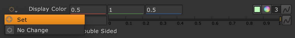
If this is turned off, the knob to its right will have no effect. It automatically turns on whenever you make a change to the knob.

The display color will not be set.

The display color will be set to green.
When a user changes a knob value they “Set” the value of the knob. If a user then resets the knob to default it will return to its default state (and value) of “No Change”.
Currently if the knob is set back to “No Change” then the value on the knob will retain the previous user “Set” value of 0.5, rather than the default state value of 1, even though it will be in the 3D viewer displaying with the default state value of 1.
In addition to exposing this concept at a knob level the new 3D system introduces a third state called “Restore Default” which is only accessible on certain knobs, such as the Draw Mode knob on the GeoDrawMode node. This is not the same as resetting a knob to its default state of “No Change”. In this case the knob (or attribute) reverts to the default value upstream (if it exists). The knob is disabled in this case as the user has explicitly chosen to use an existing value and to not control this via the knob.
Materials and Shaders
While Nuke continues to support the old way of creating materials, it now fully supports USD material networks. It’s possible to create materials in several ways such as importing USD layers containing material definitions as well as by creating nodes in the Nuke graph. Nuke now supports passing through imported materials for different renderers so it’s possible to simultaneously provide materials for both ScanlineRender and external renderers such as Prman, Arnold, VRay, etc.
At the moment however there is no support for editing the values of imported materials or for visualising the shader graphs inside material groups.
Axis, Cameras and Lights
Axis, Camera and Light nodes will now produce USD prims which can be combined in a scenegraph with other geometry objects. While these nodes can produce USD prims and scenegraph prims like a geometry node they are fundamentally different in that they do not process scenegraph by default and can be used standalone, just like before, providing transform matrices, projection matrices, and parameters for other nodes to directly access.
You can still connect up the nodes in a hierarchical fashion using the parent input and they can still be used as inputs to node that need axis or camera inputs, but the creation of USD prims is completely optional. In other words outputting USD prims is not required for the node to provide data to other nodes which directly access transform, lens or projection outputs.
These nodes are still capable of importing data from an external file source (now using the USD file I/O system so any file format USD supports can be imported) but in addition can import data from another geometry node in the same Nuke graph. In both cases a path to the desired prim is provided. Importing data works much like before where the entire animation of the source xform/camera/light prim is copied into the node knobs, effectively localising it, thus allowing it to be manipulated without affecting the original source prim. This ability to selectively localise attribute data is an important difference to geometry nodes where attribute data is only manipulated as it passes through the node. For example only the rotations of a camera can be imported, or just the translations. The imported prim can also be subframe-offset in time and the frame rate changed, and this only affects the attribute data placed in the knobs.
Local parent translate/rotate/scale knobs have been added to support the importing of transforms that are part of a parenting hierarchy without losing the prim’s local transform values. This allows an xform or camera to be unparented from any scene placement while retaining the local rotations, translations, etc.