O_ColourMatcher Example
In this example, there is a subtle color discrepancy between our stereo views and reflections that are present in one view but not the other. To fix this, we need to match the colors of the right view with those of the left using the Local Matching mode. The stereo image used in the example can be downloaded from our website. For more information, please see Example Images.
Step by Step
|
1.
|
Start Nuke and open the project settings by pressing S on the Node Graph. Select the Views tab and click the Set up views for stereo button. |
|
2.
|
Import the dance_group_disp.exr footage. This image already includes both the left and the right view, and the necessary disparity channels. |
|
3.
|
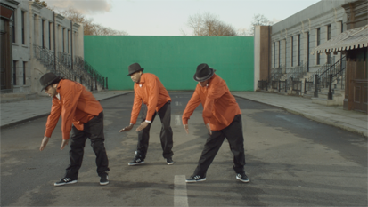
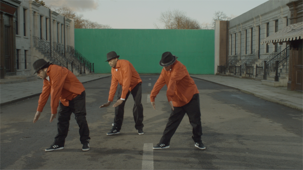
Attach a Viewer to the image. Using the Viewer controls (or the ; and ' hotkeys), switch between the left and the right view. As you can see, there is a subtle color difference between the views. |
|
|
|
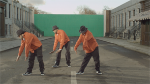
The original left view.
|
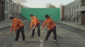
The original right view.
|
We are going to match the colors of the left view with those of the right.
|
4.
|
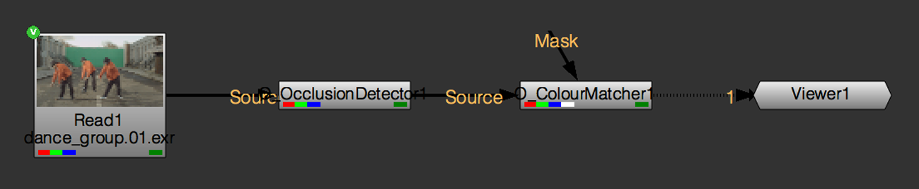
Select Ocula > Ocula 4.0 > O_OcclusionDetector to add an O_OcclusionDetector node after the stereo images. |
|
5.
|
Insert an O_ColourMatcher node after O_OcclusionDetector by selecting select Ocula > Ocula 4.0 > O_ColourMatcher. |
|
|
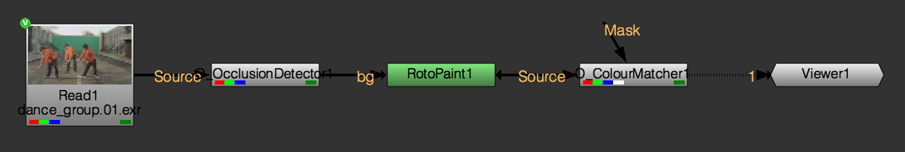
The node tree with O_ColourMatcher.
|
|
6.
|
In the O_ColourMatcher controls, you can select either Left to Right or Right to Left from the Match dropdown, depending on the direction in which you want to perform the color match. The Match menu is already set to Left to Right, which is what we want. |
|
7.
|
Set Mode to Local Matching. |
In this mode, O_ColourMatcher first divides the two images into square blocks according to the Block Size control. Then, it matches the color distributions between corresponding blocks in the two views.
As the Occlusion options are enabled in the Local Matching mode, O_ColourMatcher can produce better results in the occluded areas defined by the upstream occlusion mask. In these areas, O_ColourMatcher cannot correct the color in one view by using the color from the other. Instead, it looks for similar colors in the nearby unoccluded areas that it has already been able to match and uses the closest color it finds.
|
8.
|
View the result and switch between the two views again. Compare the new left view to the original left view by displaying the left view in the Viewer, selecting the O_ColourMatcher node, and pressing D a couple of times to disable and enable the node. Notice that the colors of the left view now match those of the right, but there are some artifacts in the middle of the image. |
|
|
The color corrected left view.
|
|
9.
|
To fix this, we are going to add more areas to the occlusion mask. Press P on the Node Graph to add a RotoPaint node after O_OcclusionDetector. |
|
|
The node tree with RotoPaint.
|
|
10.
|
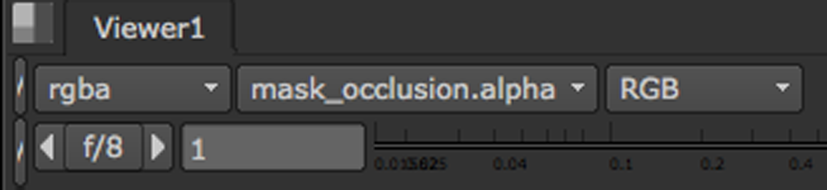
In the Viewer controls, set the alpha channel menu to mask_occlusion.alpha as shown below. |
This sets the occlusion mask that O_OcclusionDetector generated as the channel that is displayed in the alpha channel.
Next, press M on the keyboard with the Viewer selected to superimpose that channel as a red overlay on top of the image’s RGB channels.
|
|
The occlusion mask in a Viewer overlay.
|
|
11.
|
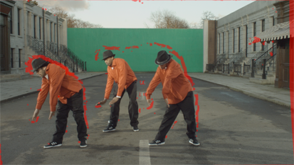
Open the RotoPaint controls and set output to mask_occlusion. Activate the Brush tool in the Viewer toolbar and paint over any areas that were producing poor results. If it helps, press D on the O_ColourMatcher node to disable it and stop it updating after each paint stroke. Pressing D again re-enables the node. |

|
|
Adding more areas to the occlusion mask.
|
|
12.
|
Press M on the Viewer to hide the occlusion mask overlay. |
|
13.
|
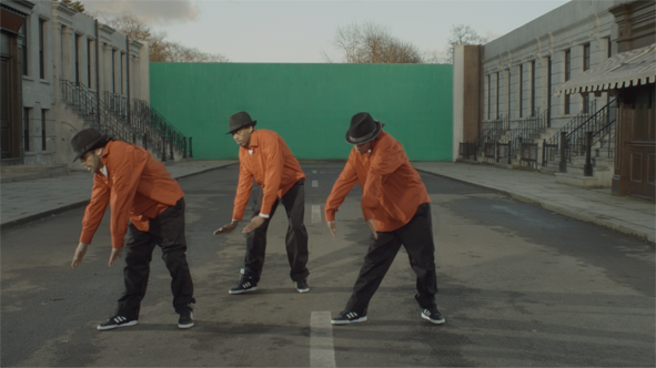
Enable and disable O_ColourMatcher to compare the original and the color corrected view. The results should now be more accurate. If you still see some problematic areas, you can add them to the occlusion mask too or adjust the Local Matching and Occlusion controls in the O_ColourMatcher Properties. |
|
|
|
The final left view.
|
The original right view.
|