Using O_VerticalAligner
To vertically align a pair of stereo images, you can several modes: Global Alignment, Local Alignment, Fix Scale, and Fix Offset. You can choose to use a mixture of these modes, for example, you can perform a global alignment and a local alignment which are concatenated into a single filter operation.
You can apply a global image transform to align the feature matches generated by an upstream O_Solver node, or you can rebuild the view(s) to remove vertical disparity calculated by an upstream O_DisparityGenerator using the Local Alignment mode.
Note: The Global Alignment mode is on by default.
To use the O_VerticalAligner, complete the following steps:
| 1. | Select Ocula > Ocula 4.0 > O_Solver to insert an O_Solver node after your stereo clip. For more information on how to use O_Solver, see Solver. |
| 2. | Select Ocula > Ocula 4.0 > O_VerticalAligner to insert an O_VerticalAligner node after either O_Solver. |
| 3. | Connect a Viewer to the O_VerticalAligner node. Your node tree should now look something like this: |
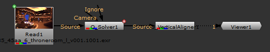
|
| 4. | Open the O_VerticalAligner controls. Under Views to Use, you can see all the views that exist in your project settings. Select the two views you want to use for the left and right eye when correcting the alignment. The two views you select are mapped for the left and right eye. |
| 5. | From the Align menu, select how to move the images to align the views: Both Views, Left to Right, or Right to Left. See O_VerticalAligner Controls for information about the Align options. |
| 6. | Select the filter to handle the vertical alignment transform, or use the default Lanczos6, which is a good sharpening and scaling down filter. For more information on the available filters, see Filter under O_VerticalAligner Controls or Choosing a Filtering Algorithm in the Nuke User Guide. |
| 7. | Enable Output STMap to include the Global or Local correction as a uv coordinate map along with alignment information. |
| 8. | From the Global section, select types of alignment you want to use. You can select preset options including Transform, Match Camera, Keystone Only, and Full. You can also select Custom and manually select the types of alignment you want to include. See O_VerticalAligner Controls for more information about the types of alignment. |
| 9. | If you want to perform a local alignment, insert an O_DisparityGenerator node after O_Solver, and select the Local Alignment checkbox in the Local section of the O_VerticalAligner controls. You can now adjust the Local controls. See O_VerticalAligner Controls for more details. |
| 10. | To view the effect of O_VerticalAligner more accurately, you can: |
• Insert an Anaglyph node between the O_VerticalAligner node and the Viewer,
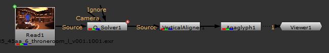
OR
• Add a StereoReviewGizmo to view alignment. See StereoReviewGizmo for more information.
| 11. | Adjust the required settings to get the best possible result. See O_VerticalAligner Controls for information about the settings. |
Analysing and Using Output Data
In all global methods except Vertical Skew, you can use the Analyse Sequence control to create output data and use the data for the following:
• Vertically align a pre-tracked Nuke stereo camera. This allows you to continue using pre-tracked cameras after your footage has been vertically aligned. Note that you can only create a vertically aligned stereo camera when a pre-tracked camera is connected to the Camera input of O_Solver.
• Create a Nuke CornerPin2D node that produces the same result as O_VerticalAligner.
The output data is also stored on the Output tab of the node controls, where you can see the transform represented as a four-corner pin and a transform matrix per view.
To analyze and use the output data, complete the following steps:
| 1. | After performing a vertical alignment, click Analyse Sequence under the Analysis section in the O_VerticalAlignet controls. |
Note: You cannot use Analyse Sequence with the Local Alignment checkbox selected.
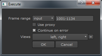
| 2. | When prompted, enter a frame range to analyze. O_VerticalAligner analyzes the sequence. |
| 3. | You can now use the output data in the following ways: |
• To output a vertically aligned camera pair, click either Create Camera or Create Rig. Create Camera produces a single Camera node with split controls to hold the left and right view parameters. Create Rig produces two Camera nodes and a JoinViews node that combines them.
• To create a Nuke CornerPin2D node that represents the result of O_VerticalAligner, click Create Corner Pin. A CornerPin2D node that produces the same result as O_VerticalAligner appears in the Node Graph.
Scripting Analysis and CornerPin Creation
Given a standard Node Graph containing your footage, an O_Solver, and an O_VerticalAligner, Ocula allows you to automate the setup of a CornerPin for a range of frames without having to manually create the required analysis frames.
The following Python script examines feature matches in the entire sequence, analyzes the vertical alignment for a given frame range for both views, and then creates a CornerPin node containing to data for the four pinned points in the Viewer.
Tip: If you don't want the analysis to continue on failure, remove the 1 after the frame range in the second Python call.
# Run the analysis pass on the Solver
nuke.toNode('O_Solver1')['analyseSequence'].execute()
# Run the analysis pass on the VerticalAligner between frames 1001 and 1085
nuke.execute("O_VerticalAligner1", 1001, 1085, 1, ['left','right'])
# Create the cornerPin
nuke.toNode('O_VerticalAligner1')['createPin'].execute()
O_VerticalAligner also has a Python tab in the Properties panel, allowing you to call Python functions automatically when various events happen in Nuke. See Help > Documentation > Python Developers Guide for more information.