VerticalAligner
Description
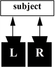
If the cameras used to shoot stereoscopic images are poorly positioned or converge (point inwards), some features in the resulting two views may be vertically misaligned. In the case of converging cameras, the misalignment may be due to keystoning. Unlike converging cameras, parallel cameras do not produce keystoning.
|
|
|
Parallel cameras do |
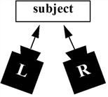
Converging cameras |
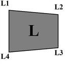
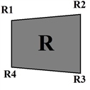
Keystoning is when an image is distorted because the angle created by converging cameras affects the perspective in the two views. As a result, corresponding points in the two views are vertically misaligned.
|
|
|
The left image. |
The right image. |
Whether the vertical misalignment was caused by poorly positioned or converging cameras, it can result in an unpleasant 3D stereo viewing experience. When a vertically misaligned stereo image is viewed with 3D glasses, the viewer’s brain attempts to line up the corresponding points in the images, often causing eye strain and headaches. To avoid this, stereo images should only contain horizontal disparity, not vertical.
O_VerticalAligner allows you to warp views vertically so that their corresponding features align horizontally. The Vertical Skew and Local Alignment options allow you to warp the views, while keeping the horizontal position of each pixel the same so that there is no change in convergence.
|
|
|
|
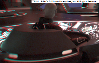
Before O_VerticalAligner. Notice that the curved line at the bottom of the image and the controls on the left are misaligned. |
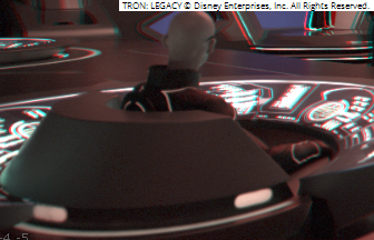
After O_VerticalAligner. Notice that the curved line at the bottom of the image and the controls on the left have now been aligned. |
There are several modes: Global Alignment, Local Alignment, Fix Scale and Fix Offset. If the none of the method checkboxes are selected in the Local, Fix Scale, or Fix Offset sections of the O_VerticalAligner controls, the Global Alignment mode is on by default.
Global Alignment Mode
In the Global Alignment mode, O_VerticalAligner performs a global transform to align the views. You can choose between several alignment types. All methods concatenate. This means that if you select several alignment types from the Global section in the O_VerticalAligner controls, their functions are combined. See O_VerticalAligner Controls for information about each alignment type.
If you have a pre-tracked Nuke stereo camera that describes the camera setup used to shoot the Source images, you can attach it to the O_Solver node and use O_VerticalAligner in the Global Alignment mode to analyze the sequence and output a vertically-aligned camera pair. This works with all global methods except Vertical Skew (which can't be represented by a camera transform). For more information, see Using O_VerticalAligner.
Local Alignment Mode
In the Local Alignment mode, O_VerticalAligner rebuilds the image per-pixel to account for any local distortions in the mirror or lens, and changes in alignment with depth using O_Solver data.
The Local Alignment mode always requires a disparity map upstream. You can create one using an O_DisparityGenerator node upstream of the O_VerticalAligner node.
Note: You can create disparity once and it is aligned to match the aligned plate. There is no need to recalculate disparity.
Fix Scale Mode
The Fix Scale method allows you to zoom the plate if the original footage was not over-scanned, and the alignment pulls black into the format.
You can scale the image to prevent pulling pixels from outside the input image. To minimize the scale change, align Both Views.
Warning: The scale has to be applied to both images, even when aligning Left to Right or Right to Left.
Fix Offset Mode
The Fix Offset method allows you to correct any convergence change that has happened on the subject to preserve the original subject parallax and hence depth.
You can shift the image to preserve the parallax at the fix-point.
Note: The Fix Offset mode requires upstream disparity vectors. If they do not already exist in the image sequence, insert an O_DisparityGenerator node to calculate them.