Search is based on keyword.
Ex: "Procedures"
Do not search with natural language
Ex: "How do I write a new procedure?"
Working with Nodes
Nodes are the basic building blocks used to represent layers, channels, and shaders in Mari. Nodes can exist individually, within Backdrop nodes, or as part of a Group (including graph layers) in the Node Graph.
Adding, Deleting, and Bypassing Nodes
You can add nodes using the Tab menu or the right-click menu. When you add a node, Mari automatically connects it to the currently-selected node.
Adding Nodes Using the Tab Menu
| 1. | Click the existing node that you want the new node to follow. |
Tip: If you don't select an existing node, the new node is added at the cursor location.
| 2. | Press the Tab key and start typing the name of the node you want to create. |
This opens a prompt displaying a list of matches.
| 3. | To select the node you want to add from the list, you can either click on it, or scroll to it with the Up and Down arrow keys and press Return. |
Tip: If you decide not to add a node, press Esc to close the node selector.
Adding Using the Right-Click Menu
| 1. | Right-click on an existing node that you want the new node to follow. |
| 2. | From the menu that opens, select the node you want to add. For example, Filter > Clamp. |
Tip: If you don't select an existing node, the new node is added at the node selector's location.
Adding Images through the Image Manager Palette
You can add images, as Tiled or Triplanar Projection nodes, to the Node Graph by dragging-and-dropping them from the Image Manager palette.
To add a Tiled node:
| 1. | In the Image Manager palette, right-click and navigate to Add to Node Graph > As Tiled. |
OR
Click and hold an image preview.
| 2. | Drag-and-drop it in the Node Graph palette. |
The image is added as a Tiled node.
Note: You can add multiple images as Tiled nodes at once. In the Image Manager palette, select multiple images and drag-and-drop them in the Node Graph palette. The images are added as Tiled nodes.
To add a Triplanar Projection node:
| 1. | In the Image Manager palette, right-click and navigate to Add to Node Graph > As TriPlanar. |
OR
Press Shift then click and hold an image preview.
| 2. | Drag-and-drop it in the Node Graph palette. |
The image is added as a Triplanar Projection node.
Note: You can add multiple images as Triplanar Projection nodes at once. In the Image Manager palette, select multiple images then press Shift and drag-and-drop them in the Node Graph palette. The images are added as Triplanar Projection nodes.
Deleting Nodes
To delete a node from the Node Graph, either:
• Select the node and press Delete (Fn+Backspace on Mac keyboards with no dedicated Delete key), or
• Select the node, right-click in the Node Graph and select Edit > Delete.
Bypassing and Disabling Nodes
Mari allows you to bypass a single node, or its inputs, and disable a selection of nodes to alter the image output as if the node(s) were removed from the node tree. Bypassing and disabling are similar, but work slightly differently.
To Bypass a single node:
| 1. | Select the target node in the Node Graph. |
| 2. | Press Ctrl/Cmd+D on the keyboard or right-click in the Node Graph and then select Edit > Bypass. |
All inputs but one are disabled in order as you repeat the bypass action, negating their effect on the node tree without removing them.
For example, cycling through the bypass modes for a Merge node with three inputs results in:
• First bypass - all inputs except Base are disabled.
• Second bypass - all inputs except Over are disabled.
• Third bypass - all inputs except Mask are disabled.
• Fourth bypass - all inputs are disabled, effectively terminating the upstream node tree.
• Fifth bypass - all inputs are re-enabled.
To Disable a node or a selection of nodes:
| 1. | Select the target node or nodes in the Node Graph. |
| 2. | Press D on the keyboard or right-click in the Node Graph and then select Edit > Disable. |
The selected nodes are disabled, negating all but their preferred input's effect on the node tree. For example, disabling a shader node only passes the diffuse input down the node tree.
Note: You can set the preferred input for a node by editing the node's .xml file. For example, to set Base as the preferred input: <Input Name="Base" PreferredInput='1'></Input>
Node .xml resides in the following locations, by platform:
• Windows: <install_directory>\Bundle\Media\Nodes\
• Mac OS X: <install_directory>/Content/Media/Nodes/
• Linux: <install_directory>/Media/Nodes/
| 3. | Press D or select Disable again to re-enable the selection. |
Selecting Nodes
Mari offers a number of options for selecting nodes. Selected nodes are highlighted in yellow.
|
Type of Selection |
How to Make the Selection |
|
Select a single node |
To select a single node, simply click on it. |
|
Select multiple nodes |
To select multiple nodes, you can either press Ctrl/Cmd while clicking on each node you want to select, or click and drag in the workspace to draw a marquee around the nodes you want to select. |
|
Select all nodes |
Press Ctrl/Cmd+A. |
Renaming Nodes
If you need to rename a node, you can either:
| 1. | Click on the node and press N or right-click on the node and select Edit > Rename Node. |
The node name becomes editable.
| 2. | Enter a new name and press Enter. |
OR
| 1. | Double-click on the node to open its properties. |
In the Name field at the top of the Node Properties panel, you should see the current name of the node.
| 2. | Delete the current name and enter a new name in its place. |
Editing Nodes
To copy, paste, and perform other editing functions in the Node Graph, you can use the standard editing keys (for example, Ctrl/Cmd+C to copy, and Ctrl/Cmd+V to paste). Copied nodes inherit the values of their parent, but these values are not actively linked. Copied nodes allow you to assign different values to the original and the copy.
When you paste nodes, Mari automatically connects them to the node that is selected before the paste operation. If you don’t want to connect to anything, click on a blank area of the workspace to deselect any selected nodes before pasting.
|
Type of Edit |
How to Perform It |
||||||
|
Copy nodes to the clipboard |
To copy nodes to the clipboard:
|
||||||
|
Cut nodes |
To cut nodes: 1. Select the node or nodes you want to cut. 2. Right-click and select Edit > Cut (or press Ctrl/Cmd+X). Mari removes the node(s) from the Node Graph and writes the node(s) to the clipboard. |
||||||
|
Paste nodes from the clipboard |
To paste nodes from the clipboard:
Mari adds the nodes to the Node Graph, connecting them to the selected node. |
Collapsing Nodes
Click the button on the right of the title bar of your node to cycle through port list modes. Changing the collapsed state of the node can help to reduce the visual complexity of your Node Graph.
Note: When the Node Graph is zoomed out, the collapsed state button can't be clicked.
| Type of Collapsed State | Description |
Not Collapsed  |
The node is fully expanded in the Node Graph, including all connected and unconnected streams.
|
Collapsed  |
The node is fully collapsed in the Node Graph and only displays the title bar, and the input and output pipes.
|
Connected Only  |
The node is fully expanded but only displays input and output channels that are connected to other nodes.
|
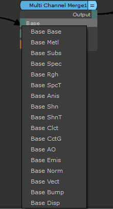
Stream Collapsed  |
Partially collapses Multi Channel Merge node inputs to display Base, Over, and Mask inputs only. Port list appears when you connect a pipe to the stream collapsed port, allowing the user to connect a pipe up to a port without fully expan ding the node.
Affects Multi Channel Merge nodes only. |
Tip: Use Shift + ~ on selected nodes to cycle through their port list modes and set all selected nodes to the same collapsed state. The Stream Collapsed mode is skipped if you have a mix of nodes selected.
Tip: Click drag the title bar of the node to move the node around in the Node Graph.
Autoplacing Nodes
The Node Graph's autoplace functionality allows you to layout upstream nodes into tidy, structured columns. If Multi-Channel Merge nodes exist in your complex Node Graph, they act as a visual backbone. Activate Autoplace functionality in the Node Graph with the L key, or by right-clicking + selecting Autoplace. As a result, your upstream nodes are laid out into columns from left to right, minimizing as many crossed connections as possible.
Tip: Autoplacing does not occur for nodes within a Backdrop unless one is explicitly selected. See Backdrop Node for more information.
Tip: If any nodes within a column outside a Backdrop node intersect a Backdrop node, the entire column is moved left until it no longer overlaps the Backdrop node.
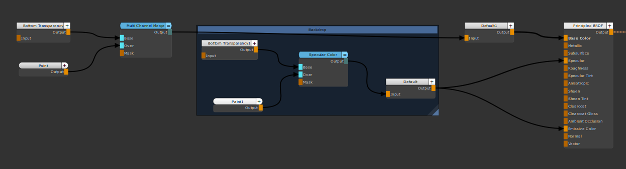
Multi-Channel Merge, Backdrop, and other nodes using Autoplace functionality in the Node Graph to restructure the nodes.
Baking to Bake Point Node
The Bake Point node allows you to:
• Control the workflow, making the export of your scene or parts of your scene easier.
• Export baked data to Geo-Channels to instantly sync the result of the upstream network to all paired Geo-Channel layers and nodes across your Node Graph.
• Increase the performance of the Canvas by baking the result of the upstream network at a specific node, making the render process faster.
• Configure the data definition of the textures.
To create a Bake Point node:
| 1. | In the Node Graph, right-click on a node where you want to bake to a Bake Point node and select Nodes > Misc > Bake Point. |
The Add Bake Point dialog opens.
| 2. | Set the Image data. |
| 3. | Click Ok. |
The Bake Point node is created and connected to the selected node.
| 4. | Double-click on the Bake Point node. |
The Bake point node panel is highlighted in the Node Properties palette, see Bake Point Node Properties for more information.
Warning: Changing colorspace settings of a channel removes any cache from all nodes of that channel.
Note: The Bake Point node is used for caching nodes, you can't paint in a Bake Point node.
Tip: Geo-Channels can be used as an intermediate caching point with the Bake Point node to allow complex node sharing without the difficulty of navigating complex shared connections in the Node Graph, by exporting the current bake data to a Geo-Channel on the object. See Adding Geo-Channels to Objects and Syncing Bake Points to Geo-Channel Nodes.
To update Bake Point nodes:
Note: The Bake Point nodes that need updating are highlighted in red.
| 1. | Double-click on a Bake Point node. |
The Bake Point node panel is highlighted in red the Node Properties palette.
| 2. | Click Bake. |
The Bake Point node is updated and turns green.
OR
| 1. | In the Node Graph, select the required Bake Point node(s). |
| 2. | Right-click and select Edit > Bake Points > Update Selected or Update Downstream. |
The Bake Point nodes are updated and turn green.
Exporting and Importing Paint and Nodes
Mari allows you to export and import Paint image data or a selection of nodes for use in other projects or layers. Paint is saved as named files or sequences and node selections are saved as .mng files.
|
Action |
How to Perform It |
||||||||||||
|
Export |
To export Paint data:
Tip: To export Paint data from multiple Paint/Bake Point nodes: |
||||||||||||
|
Import |
To import Paint data:
|
||||||||||||
|
Export nodes to file |
To export nodes to file:
|
||||||||||||
|
Import nodes from file |
To load nodes from file:
Mari adds the node(s) described by the file to the selected node. |
Customizing Node Colors and Behavior
You can customize node colors by type, such as all Filter nodes, or make changes to the appearance of the Node Graph and default node size. In the case of certain nodes, such as Dot and Backdrop, you can also customize the node's size when added to the Node Graph.
All default node parameters are stored in a file called NodeGraphStyleSheet.ini (on Windows and Mac OS X) or NodeGraphStyleSheet.conf (on Linux) which resides in your .mari or .config file depending on your operating system:
• Mac OS X:<home directory>/.config/TheFoundry/NodeGraphStyleSheet.ini
• Linux:<home directory>/.config/TheFoundry/NodeGraphStyleSheet.conf
• Windows: <home directory>\.mari\TheFoundry\NodeGraphStyleSheet.ini
Within this file there are several broad categories, which you can edit to customize the appearance of the Node Graph and the nodes it contains.
|
Category |
Function |
Example |
|---|---|---|
|
Scene |
Sets the Node Graph background color. |
SceneBackgroundColor="(50,50,50,255)" |
|
NodeStateColors |
Sets the color used to denote various node states and the general appearance of nodes. |
NodeTextColor="(0,0,0,255)" |
|
Category Colors |
Sets the color used to denote a particular category of nodes. |
FilterNodeColor="(234,234,234,255),(125,125,125,255)" |
|
Edge |
Sets the appearance and behavior of node edges when you connect pipes to nodes. |
EdgeLabelColor="(234,111,0,255)" |
|
NodeDimensions |
Sets the size of nodes that don't have specialized controls of their own, such as Dot and Backdrop. |
NodeHeight=20 |
|
AutoInsert |
Sets the size of the activation zone when you drag a node over an existing pipe to auto-insert between nodes. |
AutoInsertItemWidth=4 |
|
Backdrops |
Sets the size and appearance of Backdrop nodes. |
MinimumBackdropNodeHeight=150 |
|
StickyNoteNode |
Sets the minimum height of StickyNote nodes. |
MinimumStickyNoteNodeHeight=30 |
|
DotNode |
Sets the size of Dot nodes. |
DotNodeSize=16 |
Sorry you didn't find this helpful
Why wasn't this helpful? (check all that apply)
Thanks for your feedback.
If you can't find what you're looking for or you have a workflow question, please try Foundry Support.
If you have any thoughts on how we can improve our learning content, please email the Documentation team using the button below.
Thanks for taking time to give us feedback.