Connecting Nodes
To connect nodes, click on a node's output port to start drawing the connection, then click on the destination node's input port to connect the two nodes. Connecting also works from input to output.
When you add or paste nodes into the Node Graph, Mari automatically generates noodles between the currently selected node and the new nodes. As you build up a node tree, you may need to move these pipes or run new pipes between nodes. Simply drag either end of the pipe to the new location.
You can insert a node into an existing pipe by dropping the node onto the connection. You can toggle this behavior in the Mari Preferences dialog under Node Graph > General > Auto Insert Node.
If you are connecting multi-channel nodes, such as a Material node to a Multi-Channel Merge node, you can connect just one output to the corresponding input and the remaining outputs automatically connect to the remaining inputs.
Note: For more information on connecting nodes, see Material Node Workflow Example and Applying a Material to an Asset.
Disconnecting and Reconnecting Nodes
To disconnect, drag the head or tail of the noodle to an empty area of the node graph. To reconnect, drag and drop the arrow over the node’s input or output.
Other ways to disconnect:
• Shake the node: Simply selectand shake the node to disconnect it. Note: You can toggle shaking and adjust shake settings under Edit > Preferences > Shake to Extract. See Mari Preferences Dialog.
• Keyboard and menu: To disconnect a node or group of nodes, select the node(s) and press Ctrl/Cmd+Shift+X or right-click and select Edit > Extract
• Sever connections with the Razor: Press Y to turn the cursor into a razor. Drag the razor over the connections you want to cut. The connections turn orange and disappear. Press Y to return to pointer mode.
Note: You can detach a node from all of its connections. To do so, select the node and either press Ctrl/Cmd+Shift+X or right-click and select Edit > Extract.
Note: You can switch the first two inputs of a node by pressing Shift+X. For this to work, the node must have at least one connection.
Connecting Distant Nodes
It can be tricky to drag connections between nodes that are far apart in the node graph. Instead, you can search for the destination node once you’ve selected an output on the source node:
-
Click on the output of the node you want to connect from.
-
Hit J to search for the destination node and select the one you need.
-
Click on the destination node input to make the connection.
Note: Instead of clicking, you can also use the ‘ (backtick) key (which is usually located next to the 1 key) to select an output or input.
You can also connect distant nodes using the Teleport Broadcaster and Teleport Receiver nodes. These make a noodle-less, hidden connection between nodes, helping you construct a tidier node graph. See Teleport Broadcaster and Teleport Receiver Nodes.
Node Input Types
Nodes in Mari have different inputs depending on their function. Some are simply labeled A and B, as in the Add and Divide nodes. Some nodes, such as Ambient Occlusion and Color, require no inputs at all. The following table lists some common inputs and example nodes that employ them:
|
Input |
Function |
Example Nodes |
|---|---|---|
|
Input |
A standard input with no particular requirements. |
Brightness |
|
Mask |
Passes masking information into the associated node. |
Merge |
|
Normal |
Passes surface normals into the associated node. |
Beckman Specular, Displacement |
|
Position |
Passes positional coordinates into the associated node. |
Cube Map Projector, Oil |
|
ToView |
Connect this input to any point in the node tree to view the output up to that point. |
Viewer |
|
UV |
Passes UV coordinates into the associated node. |
Tiled Texture |
|
Vector |
Passes vector information into the associated node. |
Set Vector |
Note: You can also connect a node by dragging it over an existing pipe, Mari then auto-inserts the node between nodes. You can enable or disable this option in the Mari Preferences dialog under Node Graph > General > Auto Insert Node.
Connecting Multi-Channel Nodes
If you are connecting a source node with shader model driven output ports, such as a Multi-Channel Merge node, to another Multi-Channel node or the Output nodes within a Material node, you can connect just one stream of the source node's output ports to its corresponding input, and all sibling output ports automatically connect to the sibling stream. If an output port has an existing connection, its stream is skipped.
In the same way, when disconnecting a Multi-Channel node or the Output nodes within a Material node from a source node with shader model driven output ports, all sibling input ports also disconnect from their corresponding sibling output ports. If an output port is connected to a different node, then its connection is maintained.
Note: For more information on Materials and Output nodes, see Material Node Workflow Example
|
|
|
|
Connecting a Material node |
Connecting a Multi-Channel Merge node |
If one or both of the Multi-Channel nodes are Stream Collapsed  , you can still connect all the channels at once by dragging the connection from the output port to the input port on the other Multi-Channel node. Once connected, you can expand the nodes to see the full connections.
|
|
|
|
Connecting a Stream Collapsed Material node |
Connecting a Stream Collapsed Material node |
Note: For information about collapsing Multi-Channel nodes and making connections, see Collapsing Nodes.
Hold Shift to connect just one output port without the others connecting automatically.
|
|
|
|
Shift + Click to connect just one stream |
|
Hold Shift to disconnect just one output port without the others disconnecting automatically.
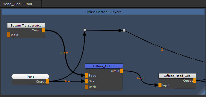
Bending Connecting Arrows
Complex Node Graphs can become difficult to read with pipe overlaps, but Mari allows you to bend pipes using a specialized node called Dot. The Dot node doesn't have any special controls like regular nodes, but it can be used to direct pipes away from congested areas of the Node Graph.
To add a Dot node, select the node before the connector you want to bend and then, either:
• press Tab and type Dot to add a Dot node,
• right-click and select Nodes > Misc > Dot, or
• hold Ctrl/Cmd and click the yellow highlight on the required pipe.
A Dot is placed after the selected node, allowing you to bend the pipe as required by dragging the Dot to a new position in the Node Graph.