Search is based on keyword.
Ex: "Procedures"
Do not search with natural language
Ex: "How do I write a new procedure?"
Using Selection Modifiers
The following tools make it easy to work with selections in Modo.
Convert Selection
The Convert Selection tool sets a new selection mode specifically, using the content of the current selection to define the new one. You convert between selection types using the Alt key as a modifier. For example, if you have polygons selected in the viewport, holding the Alt key changes the option buttons on the Modo Modes toolbar to read Convert. Press the Convert button, where Vertices was previously displayed, and the current polygon selection is converted to a vertex selection. This way you can quickly access all the vertices that were part of the original polygon selection. The conversion types are:
• Vertex : edge - selects edges defined by the selected points.
• Vertex : polygon - selects any polygons defined by the currently-selected points.
• Edge : vertex - selects points of all selected edges.
• Edge : polygon - selects polygons that are completely surrounded by selected edges.
• Polygon : vertex - selects points of all selected polygons.
• Polygon : edge - selects all the edges of the currently-selected polygons.
It's also possible to convert from a Material selection to any of the component level selections or the other way around.
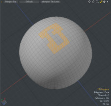
Polygon Selection Fill
The Polygon Selection Fill tool selects the entire area within an existing enclosed selection. This tool is very similar to the Select Connected (] key) tool but fills in a selection outline instead of selecting the entire surface. To apply, make a selection that represents the outside perimeter of the desired selection area, and then press the Ctrl/Cmd+Shift modifiers and double-click inside the desired area to fill. The perimeter area must be fully connected, but it is not necessary that it be perfectly rectangular.
|
|
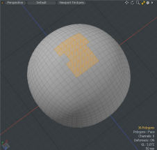
Grow Selection (Shift+Up Arrow)
The Select > Grow tool expands, or "grows", the selected elements by selecting all unselected geometry elements directly contiguous with the selection. Grow selection is mapped to Shift+up arrow so you can quickly expand your selection set. This tool works with all elements of geometry (Vertices, Edges, and Polygons) and is the functional opposite of the Select > Shrink tool.
Shrink Selection (Shift+Down Arrow)
The Select > Shrink tool reduces the selection by deselecting elements that are at the "outside" of the currently-selected elements. This has the effect of "shrinking" the selection set to a smaller size. The keyboard equivalent of this tool is mapped to Shift+down arrow. This works with all geometry elements (Vertices, Edges, and Polygons).
Note: It is possible to shrink your selection to nothing.
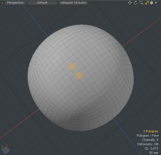
Select More/Less (Up/Down Arrows)
Selects the next plausible element. Select at least two polygons, edges, or vertices on your mesh item and then click the Up or down arrows to increase your selection. If a polygon was skipped then the next plausible element select would also skip a polygon.
Note: It is possible to deselect everything.
|
|
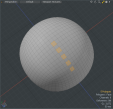
Select Loop (L key)
The Select Loop tool selects a continuous span of quadrangular polygons, edges, or vertices, depending on the selection mode. For polygons, select two adjoining polygons to define the loop direction and press the L key to select the entire loop. If not a full loop, selection terminates at non-standard geometry intersections.
|
|
For edge selections, a single edge can be selected and then press L to select the entire connected loop. If it is not a connected loop, the selection terminates at a multi-edged intersection. Edge loops can also be automatically selected by double-clicking on the target edge. Pressing Ctrl+Shift+double-click extends the loop beyond multi-edged intersections, based on the angle threshold, resolving toward the direction of the edge that is nearest to parallel with the adjoining edge.
For vertices, a loop can be defined by selecting two consecutive vertices and pressing L to select the loop, terminating in the same way as an edge loop.
Procedural Select Loop
You can take a selection based on a previous selection operation and apply the mesh operation Select Loop. Once added, you can apply a previous selection operation in your Mesh Operations list to a polygon, edge, or vertices selection.
Example
| 1. | In the Model layout, open the Basic tab on the left panel, and Ctrl/Cmd + click on the |
| 2. | On the right panel, click on your mesh item, and name it Polygons. |
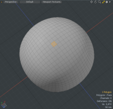
| 3. | Under the layout menu bar, click Polygons, and select two polygons on the mesh item. |
| 4. | Open the Mesh Ops tab and click Add Operator. |
Tip: If the Mesh Ops tab is not visible on the right panel, click the More Tabs or New Tab icon and select New Tab > Data Lists > Mesh Ops. 
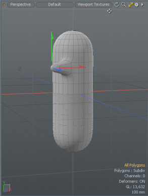
| 5. | Double-click Mesh Operations > Polygon > Polygon Extrude. |
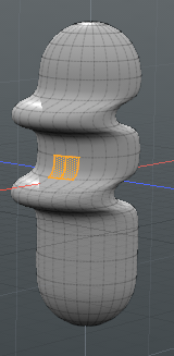
| 6. | Open the Polygon Extrude tab on the Properties tab and set Extend X to -200 mm. |
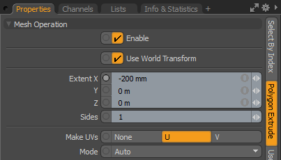
The selected polygon extrude from the cylinder.
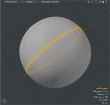
| 7. | Expand the Polygon Extrude > Selection, click (Add Selection), and double-click Modifier Mesh Operations > New > Selection > Select Loop. Alternatively, type Loop in the Search All field and double-click Select Loop. |
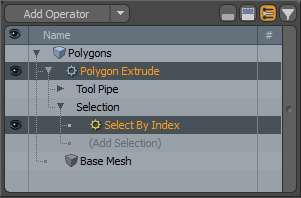
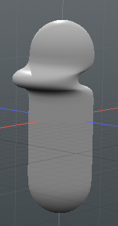
The loop selection is made and the polygons are extruded.
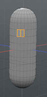
| 8. | Ensure that Polygons selection mode is active and click + drag on the mesh item to select two other polygons. |
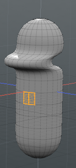
| 9. | On the right panel, expand Polygons > Polygon Extrude > Selection, and select the Select by Index. |
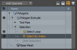
| 10. | In the Properties panel, on the Select By Index tab, and click Add. |
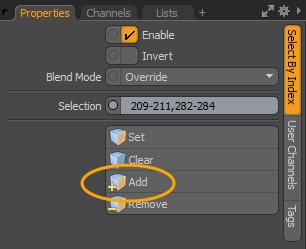
The previous selection operation is applied to your new selection.
Invert Selection ([ key)
Accessed through the Select > Invert menu, this tool switches the state of all polygons, edges, or selected vertices. The selected elements become unselected and the unselected become the selected. Toggle the selection using the Invert shortcut key [ (left square bracket).
|
|
Alternatively, you can add the Invert tool as a procedural mesh operation. Open the MeshOps tab on the right panel, click Add Operator and double-click Mesh Operations > Selection > Invert.
Select Connected (] key)
Accessed through the Select > Connected, this tool lets you quickly expand geometry selections to include all elements physically contiguous with the selection. This is a very handy workflow for selecting mesh geometry. You simply click to select a single polygon, edge, or vertex, then press ] (right square bracket) and the entire piece of geometry is selected.
Tip: While in Polygon or Vertex selection mode, you can also simply double-click on a vertex or polygon to select all connected elements.
|
|
Alternatively, you can add the Select Connected tool as a procedural mesh operation. Open the MeshOps tab on the right panel, click Add Operator and double-click Mesh Operations > Selection > Select Connected.
Select Between (Shift+G)
The Select Between tool requires that two polygons or edges are selected prior to triggering the tool. Once the tool is triggered it completes the selection between the two based on the shortest distance between them. Only a single row is selected, if the initial polygons or edges were on the same loop. Polygons in adjoining rows or columns would create rectangular selection.
|
|
Boundary Edges
With polygons selected, this tool selects all the edges around the boundary edge of the polygon set. If no polygons are selected, it basically selects all the non-manifold edges of the mesh, which can be useful for finding holes. The mechanism is simply to select all edges bordered by an odd number of selected polygons. This tool works on both continuous and discontinuous selection sets.
This tool is also available on the Select > Boundary menu or from the Statistics tab of the Info and Statistics viewport, by expanding the Edges > By Boundary entry. For more information, see Select by Info and Statistics.
To select a polygon boundary do the following:
| 1. | Select the polygons on the mesh. |
| 2. | Press the Ctrl/Cmd key. |
Notice the Edge button now is labeled Boundary.
| 3. | Click the Boundary button. |
|
|
Select Symmetrical
This command allows you to select any geometry that is symmetric to the current selection. To use the command:
| 1. | Make a vertex, edge, or polygon selection on your mesh. |
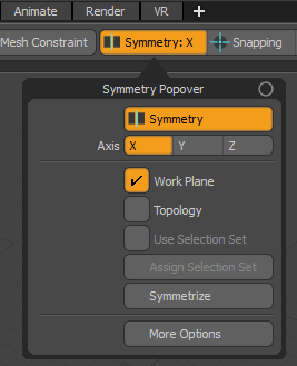
| 2. | Enable Symmetry by clicking the Symmetry button above the 3D viewport. |
By default, the selected axis is X. To change the axis, hold down Alt. This changes the button to Options. Click it, then in the Symmetry Popover, select the required Axis.
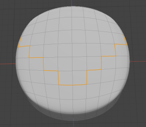
| 3. | In the menu bar, click Select > Selection Commands > Symmetrical to activate the tool. |
This adds symmetrically-corresponding vertices, edges, or polygons to your current selection.
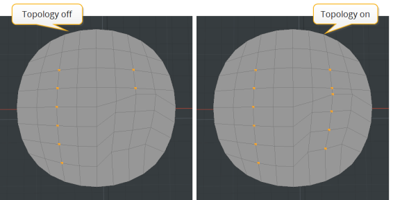
When your mesh is mostly, but not entirely symmetrical, Modo doesn't always find all symmetrical elements. In such cases, enable Topology in the Symmmetry Popover. This uses a topological matching of components. For more information on working with Symmetry, see Symmetry.
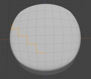
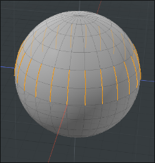
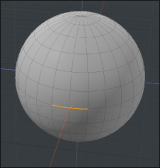
Select Ring (Alt+L)
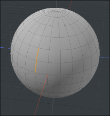
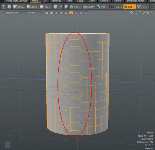
Geometric selections can be expanded to include all vertical or horizontal vertices or edges adjacent to the selection across quads. For example, in a sphere, when two vertical edges are selected.
The Ring selection highlights all the vertical edges along the same selection direction around the geometry.
| Before | After |
|
|
|
|
|
|
Direct Modeling Select Ring
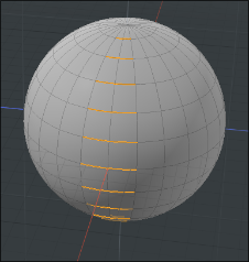
| 1. | In the 3D viewport, select two vertical vertices adjacent to each other on your mesh item. |
For more information about selection modes, see Selecting Items.
| 2. | From the main menu, click Select > Ring. |
Alternatively, press Alt+L.
The ring selection highlights all the vertices along the same selection direction around the geometry.
Procedural Select Ring
We'll apply the Select Ring mesh operation to a previous Edge Bevel operation. You can see how easy it is to apply the mesh operation to the same selection direction around the geometry.
To apply the Select Ring tool:
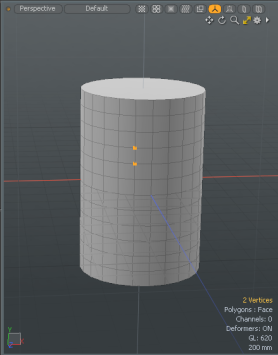
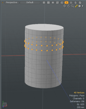
| 1. | Add a Cylinder to your scene. Using the Model layout, open the Basic tab on the left panel, and Ctrl/Cmd + click |
| 2. | With Edges selection mode active, select two parallel edges. |
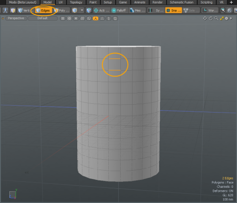
| 3. | On the right panel, open the MeshOps tab, click Add Operator, and double-click Mesh Operations > Edge > Edge Bevel. |
Tip: If the Mesh Ops tab is not visible on the right panel, click the + button on the right of the tab names, and select Data Lists > Mesh Ops.
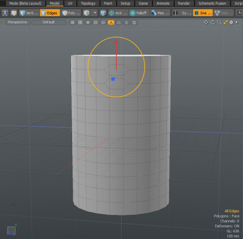
| 4. | In the 3D viewport, move the handles to create a bevel, and press Esc to drop the tool. |
| 5. | On the Mesh Ops panel, expand Edge Bevel > Selection > and click (Add Selection). |
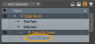
| 6. | In the Add Operation dialog, double-click Modifier Mesh Operations > New > Selection > Select Ring. |
Tip: To quickly locate a mesh operator, type the name of the tool in the Search All field. 
| 7. | On the Mesh Ops panel, select the mesh item. |
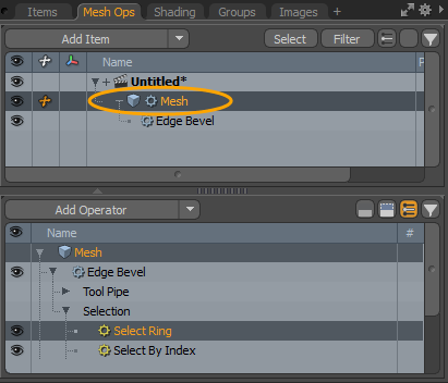
The Edge Bevel, originally applied only to the top two edges, is applied to the ring of edges along the same direction around the geometry.
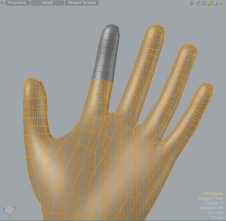
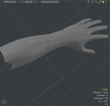
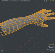
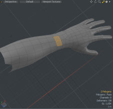
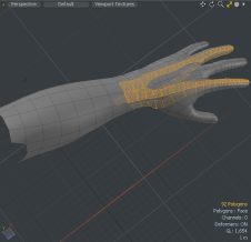
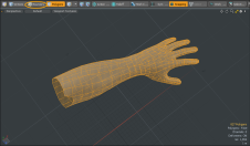
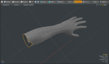
Select Close Loop (Shift+])
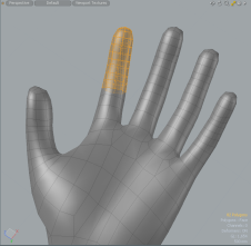
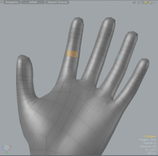
The Select Close Loop tool requires that two polygons are selected prior to triggering the tool. Once the tool is triggered it completes a loop selection using the two initial polygons to set direction and then selects all polygons on one side of the loop. The selection of the additional polygons is based on which side has fewer total polygons. For example, to select all polygons on a finger from the knuckle to the finger tip, you would select two polygons just above the knuckle, then apply the tool.
|
|
Since the finger itself has fewer polygons than the rest of the hand this is the side that is selected. This is generally the solution you are looking for, however, in the case that it's the opposite side of interest, the Select Close Loop tool can simply be followed by Select Invert.
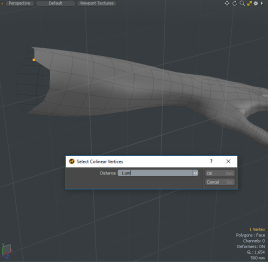
Select Colinear
The Select Colinear tool selects any extraneous vertices across a polygon's boundary, making for easy removal. To use, select the tool from the menu bar Select > Colinear and a pop-up dialog asks you to define a distance. Click OK to execute the tool, resulting in the selection of all colinear vertices. In the example below, a vertex is selected in the area of the mesh which is not lying in the same straight line or linear sequence.
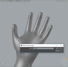
Select Coplanar
The Select Coplanar tool selects the edges between polygons that fall within a flatness range of a selected polygon. To use, select a polygon, and then select the tool from the menu bar Select > Coplanar and a dialog box appears, allowing you to specify a flatness limit (threshold between opposing triangle pairs). Click OK to execute the tool, resulting in an edge selection based on your input.
|
|
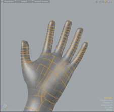
Coplanar Polygons Tool
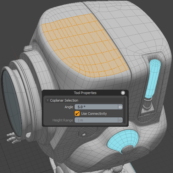
The Coplanar Polygons tool allows you to select neighboring polygons on the same plane as the original selection. This tool works similarly to the Coplanar Falloff.
To use the tool:
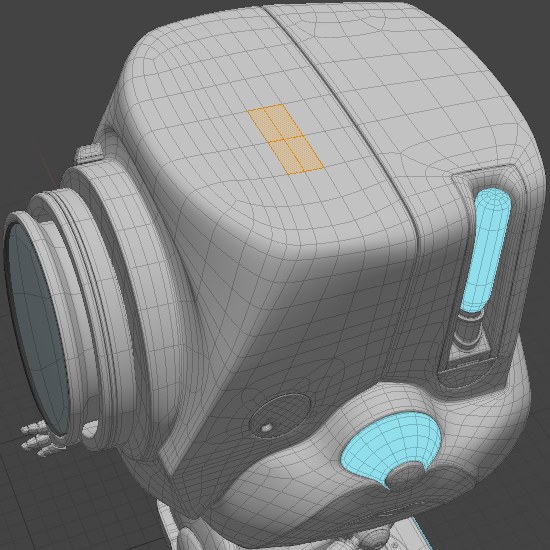
| 1. | With your scene open in the Modo layout, enable Polygons selection mode and select one or more polygons on your mesh. |
| 2. | In the Modeling toolbox's Select tab, click Coplanar Polygons Tool. |
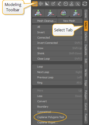
Note: You can also access the tool from the menu bar. Click Select > Selection Commands > Coplanar Polygons Tool.
| 3. | Click in the viewport to activate the tool. |
This selects all polygons that are coplanar with the original selection.
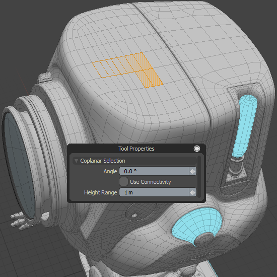
When the tool is active, you can adjust its settings to influence which polygons are selected.
| 1. | Click Tool Properties on the left panel. |
This opens the tool properties.
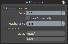
You can adjust the following properties:
|
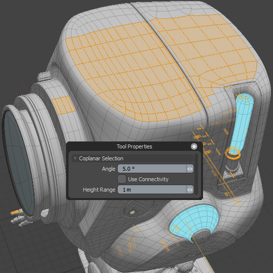
Angle |
Determines the range outside the selected area to attenuate the effect of the tool. Increasing the value selects more polygons.
|
||||||
|
Use Connectivity |
When enabled, only connected elements are selected. Unconnected elements within range are ignored.
|
||||||
|
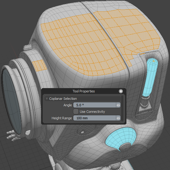
Height Range |
Determines the maximum threshold to include polygons with the same normal, but not on the same infinite plane. This is used when Use Connectivity is disabled. At 0 m, the tool selects only polygons on the infinite plane of the source polygons. When Height Range is higher than 0, the tool selects polygon with same normal direction with different height position in the specific range. The default value is 1 m.
|
The Coplanar Polygons Tool's procedural equivalent is the Select Coplanar Polygons mesh operation. For more information, see Select Coplanar Polygons.
Select Diagonal
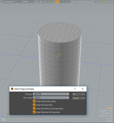
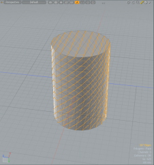
The Select Diagonal tool selects edges to share triangle pairs. This is useful when you want to convert triangles to quadrangles. You can convert triangles to quadrangles by deleting the selected edges.
|
|
To use, select an edge, and then select the tool from the menu bar Select > Diagonal... A dialog appears allowing you to specify options. Specify the options and click OK.
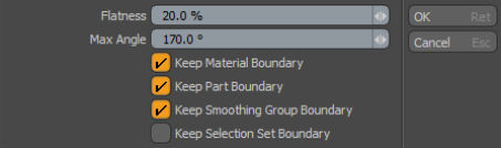
• Flatness - this is the Coplanar flatness threshold between opposing triangle pairs, designating whether the edge is selected or not.
• Max Angle - this is the maximum angle for the corners of a quadrangle from the triangle pair.
• Keep Material Boundary - when enabled, edges that fall along material boundary are not selected.
• Keep Part Boundary - when enabled, edges that fall along a part boundary are not selected.
• Keep Smoothing Group Boundary - when enabled, edges that fall along a smoothing group boundary are not selected.
• Keep Selection Set Boundary - when enabled, selection set boundary are not selected.
Select by Info and Statistics
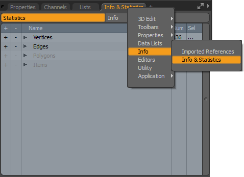
You can also select elements by using the Info and Statistics viewport. To open this viewport, on the right panel, click the plus button and select Info > Info & Statistics. For more information, see Info and Statistics.
Sorry you didn't find this helpful
Why wasn't this helpful? (check all that apply)
Thanks for your feedback.
If you can't find what you're looking for or you have a workflow question, please try Foundry Support.
If you have any thoughts on how we can improve our learning content, please email the Documentation team using the button below.
Thanks for taking time to give us feedback.