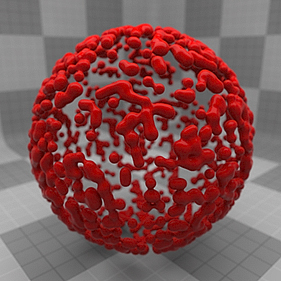
The Blob item provides a means to procedurally create blobby meta-ball like shapes; combinations of spherical forms with a smooth, interpolated curved surface covering them. The positions of individual blob shapes are determined by the vertices of a Particle Source item, where each vertex in the Particle Source produces a single blob (see Particle Source under Geometry for more information).
The form itself is dependent on the radius of the Blob particles and the distance between adjoining vertices, as the surfaces get closer together, they tend to join their surfaces (think like water droplets when they get close to each other). The resulting surface can be further controlled with the addition of textures added through the Shader Tree, producing complex surfaces very easily.
A Blob item is added to a scene using the Add Item function found in the Item List. Left-click the button itself to open the dropdown and then select Volumes > Blob. Once added, the item appears at the bottom of the Item List viewport. When selected, a number of attributes controlling the shape appear in the Properties viewport.
Normally, surfaces are applied through the use of polygon tags that define masks in the Shader Tree controlling material placement. Blobs, however, are a procedural surface created at render time and have no user selectable polygons to apply a tag to, so surfacing is applied to the Blob item through the use of an Item Mask.
You can quickly create an Item Mask by right-clicking on the Blob item in the Items list and choosing the Create Item Mask option from the contextual menu. You can then add Materials and other Shader Tree items, setting the appropriate Effect for each layer to build up surfacing attributes, just as you would for any other surface.
You can also control additional attributes of the Particle Source that are not surface specific, such as Particle Size and Particle Density, by creating an additional Item Mask and applying texture layers set to the appropriate Effect under the FX Item of the Shader Tree. For more information, see FX Item.
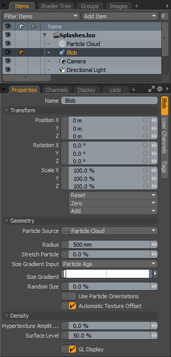
Name - This data field displays the current item name. You can easily change it by left-clicking within the field and typing the new name.
Position - An Item transform that allows you to numerically position the item in XYZ space. By default, Position transforms originates from the Center position.
Rotation - An Item transform that allows you to numerically set the rotation of the item. By default, Rotation transforms originate from the Center position.
Order - Allows you to set the order that rotations are applied to the camera item. Changing the order in which rotations are applied can sometimes help to reduce, or eliminate, gimbal lock.
NOTE: The Order control is only displayed after you have selected a Rotation.
Scale - An Item transform that allows you to numerically set the size of the item. By default, Scale transforms originate from the Center position.
Reset - Click to reset the selected transform values to (0,0,0), returning the items back to their default state.
Zero - Click to reset the selected transform property values to 0, leaving the Center position and Mesh position intact.
Add - Transform Items are the channel groups associated to an item that store its transform values, controlling its position, rotation and/or scale. By default, new items do not have any transform items associated with them, even though they are visible within the Properties panel. This is useful as an optimization, as the necessary transforms are added on an as-needed basis, reducing scene overhead.
There are several ways to add them. One is by simply transforming the target item with one of the various transform tools (or by editing the values input fields). This action automatically adds the selected transform item to the Channels viewport list. The Add function can also be used to add the selected set of transforms to the Channel list, while keeping the default 0,0,0 values (a necessary step for Referencing - in order to override the channels, they must first exist).
Particle Source - When a Sprite item is added to a scene, it is represented by a single locator type point at the World Origin, producing a single sprite image. To produce additional sprites, define a Particle Source, which can be any Mesh Item layer that contains vertices, where each vertex position is used to determine the position of the sprite particle. Any type of geometry can be used, such as single point polygons, vertices, two-point polygons, and regular polygons, however, only the vertex positions of any component are used.
Source layers can be normal geometric forms, point clouds that are imported or created using the Particle Cloud item, or any of the Particle Tools. They can be imported particle simulations controlled by way of an MDD deformer, RealFlow Particles, or an Alembic format data file.
Radius - This option determines the base size of the sprite image. From here, the size can be altered using the Random Size option, the addition of a Particle Size Vertex Map that allows you to paint the scale for individual particles interactively, or with the application of a texture layer, under the FX Item of the Shader Tree, set to control Particle Size.
Stretch Particles - This percentage controls the scale of particle stretching based on velocity. Values are additive to the base value, so a Stretch Particle value of 100% produces a particle that is stretched to twice its length (200% altogether).
Size Gradient Input - This control provides a means to define an input parameter in which to apply the Size Gradient, determining the scaling of the resulting volume, based on the chosen parameter. You can choose from a number of input parameters specific to Volumes and Particles, such as Texture Value (Density), Distance, and Particle Velocity.
Size Gradient - This is gradient slider allowing you to refine gradient value keys without having to leave the basic Modo interface. In much the same way as keyframes store transform values for items, gradient keys store values and softly attenuate between the defined key positions.
You can add keys by middle-clicking along the gradient. Keys are then adjusted by left-clicking and dragging to a new position. The gradient bar directly underneath provides a visual reference to the values being generated by the gradient itself. The defined values act as a multiplier of the final volume size on the preceding Size Gradient Input option.
Random Size - This option controls the amount of randomness added to the scale of each individual particle blob. The amount is determined by a scale percentage, so a setting of 25% adjusts the scale of the base radius size by an amount of 0%-25% randomly across all particles, 50% adjusts the size by 0%-50% randomly across all particles, and so on.
Use Particle Orientations - When enabled, aligns the particle to the direction vector from the particle source. The direction vector is usually the surface normal for surface particles, or the particle velocity vector for simulation particles (such as from RealFlow).
NOTE: In the case of blobs, this option is disabled by default as it adds to render times (an increase of ~30%), so don't use it if you don't need it.
Automatic Texture Offset - When enabled, adds a different offset to the hypertexture for each particle, so that individual particles look different.
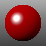
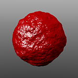
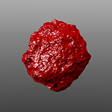
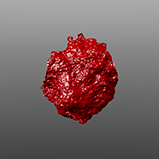
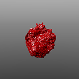
Hypertexture Amplitude - Determines the amplitude (intensity) of a Volume Density texture layer applied to the blob volume. The higher the value, the more you see the effect of the density texture. It's similar in concept to displacement amplitude, but applies to volumes.
|
|
|
|
|
|
| Amplitude 0% | Amplitude 25% | Amplitude 50% | Amplitude 75% | Amplitude 100% |
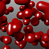
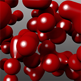
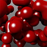
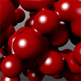
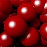
Surface Level - The surface level option determines the height of the limit surface, which in-turn controls how smooth or abrupt the transitions are between neighboring blobs. Low values produce smoother blobs that are slightly smaller, and higher values produce more spherical shapes that are slightly larger. At 100%, individual blobs no longer blend, but look like a collection of spheres instead.
|
|
|
|
|
|
| Surface Level 0% | Surface Level 25% | Surface Level 50% | Surface Level 75% | Surface Level 100% |
GL Display - This option toggles the display of the Blob proxy in the 3D OpenGL viewport. When enabled, you can see an approximation of how the blob particles render (the default state), but in heavy scenes you may find it useful to disable this option to increase scene interactivity or reduce overall visual clutter.