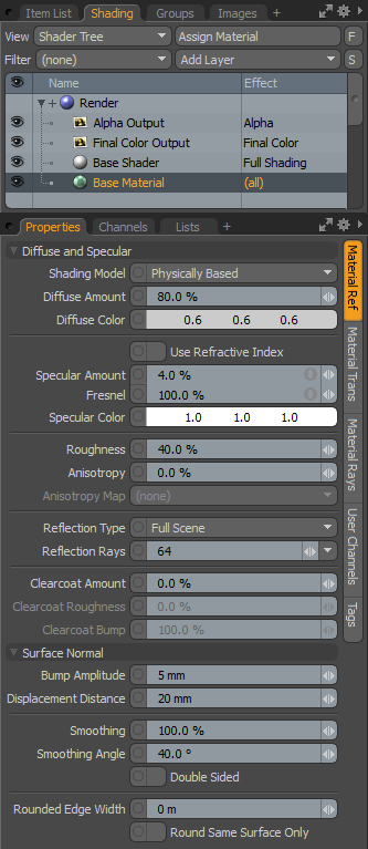
The Material item is the default general purpose Shader Tree layer that controls all the various standard shading attributes for a surface's final rendered look, be it shiny, dull, reflective, or transparent. It contains channels to control Diffuse, Specular, Reflections, and Transparency, among other surfacing attributes. Every new scene, by default, contains a single material layer called the Base Material that effectively shades the entire scene until material tags are defined, limiting materials and shading to specific surfaces.
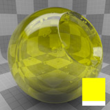
Due to the number of attributes for the Material layer, its property form is divided into three sub-tabs:
• Material Ref (Reflective) - contains all material attributes that impact how much light is reflected from the surface, such as Diffuse, Specular, and Mirror reflected light.
• Material Trans (Transmissive) - controls how light is transmitted through a material such as Transparency and Subsurface Scattering.
• Material Rays - used when controlling rays for clipping and Volumetric rendering.
In addition to these sub-tabs, nearly all material properties can be controlled through a texture bitmap or procedurally by creating a new texture layer and setting the desired Effect you wish to control. For information more on adding layers and setting their Effect, please see Shader Tree.
|
Option |
Description |
|||
|---|---|---|---|---|
|
Diffuse and Specular |
||||
|
Shading Model |
This option controls how light and surfacing attributes are evaluated for final rendering. These Shading Models are also know as Bidirectional Reflectance Distribution Functions, or BRDFs. Each Shading Model subtly changes how Specular, Fresnel, Reflection, and illumination falloff are computed during rendering: • Physically Based - exhibits the most faithful highlight shape and Fresnel falloff shading and is based on the Generalized Trowbridge-Reitz BRDF model, popularized by a number of famous movie studios because of its ability to produce realistic surface shading. • Traditional - allows you to match surfaces to those rendered using Modo's legacy BRDF, based on the on the Phong-Blinn model. • Energy Conserving - automatically controls the diffuse/specular/reflection mix to produce realistic shading results, but for most cases it is superseded by the Physically Based model for its superior results. This is another legacy Shading Model used when the Conserve Energy option was enabled. It is based on the Ashikhmin-Shirley BRDF. |
|||
|
Diffuse Amount |
In the real world, all surfaces absorb certain wavelengths of light while reflecting others. The light that is reflected is what we perceive as the color of the object. This is known as Diffuse light. The Diffuse Amount attribute acts as a multiplier to the Diffuse Color setting determining how much of that light is reflected from, or absorbed by, the surface. A setting of 100% returns the same value defined as the Diffuse Color value when lit by a pure white light at 100% intensity. A Diffuse Amount of 50% appears half as bright under the same light as it would only returning half of the light bounced from the surface. All surfaces, no matter how shiny absorb at least a small amount of light, so the default value is defined as 80%. |
|||
|
Diffuse Color |
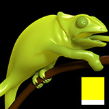
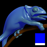
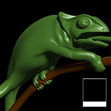
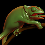
This setting defines the color of the surface when lit by a pure white light source, multiplied by the Diffuse Amount. This attribute is effectively the color of your object, representing the light that bounces from the surface. Diffuse colors can also be driven beyond traditional color space into high dynamic range values by applying Diffuse Amounts over 100%, but they will not be physically plausible at that point. |
|||
|
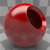
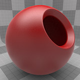
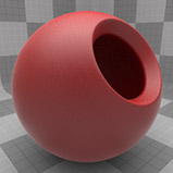
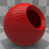
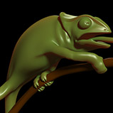
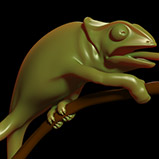
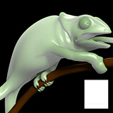
Diffuse Roughness |
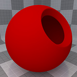
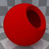
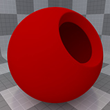
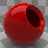
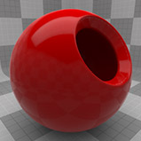
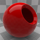
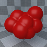
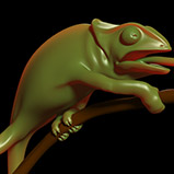
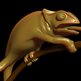
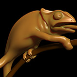
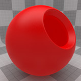
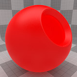
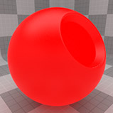
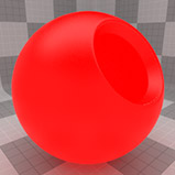
Extremely matte surfaces, such as stone, concrete, or plaster, reflect light very differently than smooth or glossy surfaces, such as glass or plastic. This is because, on a microscopic level, the matte surface is actually quite rough, spreading the light outwards making the surface appear more flat. Diffuse Roughness aims to simulate this microscopic roughness effect by modifying the standard shading model, producing a more believable matte surface. A value of 0% disables the effect, while values above zero increasingly produce a rougher, more matte surface. Since Diffuse Roughness simulates a lack of Specular, it is best applied when the Specular Amount is 0% (see image examples below). NOTE: The Diffuse Roughness attribute is only enabled for the Traditional and Energy Conserving legacy shading models. |
|||
|
|
|
|
|
|
| Diffuse Roughness 0% | Diffuse Roughness 25% | Diffuse Roughness 50% | Diffuse Roughness 75% | Diffuse Roughness 100% |
|
Use Refractive Index |
When enabled, use the defined Refractive Index value to set the specular/reflectivity amount for a surface. The main benefit being that the Refractive Index is a commonly measured value posted in several online databases used to define the physical accuracy of surfaces. |
|||
|
Refractive Index |
This option defines the Refractive Index (IOR) of the surface, that is, how light rays bend through the volume and, when Use Refractive Index option is enabled, the amount of surface specularity/reflectivity. |
|||
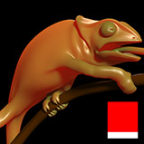
|
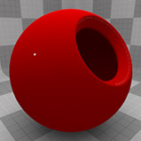
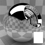
Specular Amount |
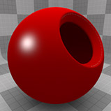
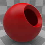
In the real world specular highlights are the reflections of very bright light sources on a surface. How these reflections spread over a surface tells you a lot about that surface, whether it is shiny or dull, smooth or rough. Modo simulates this reflection with these five settings: • Specular Amount • Fresnel • Specular Color • Roughness • Anisotropy Generated only from direct light sources, the Specular Amount is multiplied with the Specular Color to create the overall rendered result. Increasing the value results in a more intense highlight while decreasing the value mutes the effect. When this value is 0%, the Specular Color, Roughness, and Anisotropy controls are disabled and specularity is not calculated. |
|||
|
|
|
|
|
|
| Specular Amount 0% | Specular Amount 25% | Specular Amount 50% | Specular Amount 75% | Specular Amount 100% |
|
Fresnel |
At glancing angles (any surface that is near perpendicular to the direction the camera is facing) many types of surfaces increase their reflectance values. The Fresnel setting (pronounced fra-nell) realistically increases the specular amount at these glancing angles to produce a physically plausible result. |
|||
|
Specular Color |
This function defines an RGB value that tints the specular highlight. |
|||
|
|
|
|
|
|
|
Roughness |
Surfaces can be very different from each other, such as a rubber ball, a plastic cup, and a terracotta brick. These are all seemingly smooth surfaces, but on a microscopic scale their surfaces are very different. The microscopic surface variations has a direct effect on the way the light reflects off of each surface. The Roughness setting simulates these microscopic differences making surfaces appear more dull or rough, or shiny and smooth. It also affects both the Specular highlight as well as ray traced and environmental reflections (reflection roughness only occurs when the Blurry Reflection option is enabled). Increasing this value widens the reflection, creating a much broader specular highlight. When used with Blurry Reflections, a very high value yields a very distorted reflection. |
|||
|
|
|
|
|
|
| Roughness 0% | Roughness 25% | Roughness 50% | Roughness 75% | Roughness 100% |
|
Anisotropy |
Millions of microscopic scratches on a surface distort highlights and reflections over their surface parallel to the directions of the scratches. The Anisotropy value affects the highlights, simulating this effect. Anisotropy is controlled by a UV map or further controlled by a texture maps when the layers effect is set to the Anisotropy Direction. It can be caused by many man-made processes, such as machining metal and also appears in textiles where shiny threads spread the highlight over a surface. |
|||
|
|
|
|
|
|
| Anisotropy 0% | Anisotropy 25% | Anisotropy 50% | Anisotropy 75% | Anisotropy 100% |
|
Anisotropy Map |
The UV map dropdown allows you to choose which map determines the anisotropic direction. The U direction (horizontal) defines the direction of the virtual scratches for positive Anisotropy values. |
|||
|
Match Specular |
When enabled, match the Reflection Amount and Fresnel values to the like settings defined under Specular Amount. A specular highlight is simply the reflection generated by Modo's direct light sources, so naturally, to be correct, both would need identical values. With this checkbox, you only need to adjust the values once. Additionally, this option takes into account any Texture layers with an effect defined as Specular Amount or Specular Color. NOTE: When this option is enabled, all reflective shading is derived from the Specular channel so texture layers defined as Reflection Amount or Reflection Color are ignored. |
|||
|
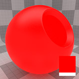
Reflection Amount |
This option determines how reflective a surface is. At 100%, the surface is effectively a perfect mirror whereas lower values create a more muted reflection effect. NOTE: Reflection is an additive effect, so reducing the Diffuse Amount is necessary to avoid overly bright surfaces. This is done automatically when using the Physically Based or Energy Conserving shading models, and as such, these attributes do not appear in those cases. |
|||
|
|
|
|
|
|
| Reflection Amount 0% | Reflection Amount 25% | Reflection Amount 50% | Reflection Amount 75% | Reflection Amount 100% |
|
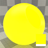
Fresnel |
At glancing angles (any surface that is near perpendicular to the direction the camera is facing), reflectance values increase. The Fresnel setting realistically increases the reflection amount at these glancing angles producing a physically correct surface. |
|||
|
|
|
|
|
|
| Fresnel 0% | Fresnel 25% | Fresnel 50% | Fresnel 75% | Fresnel 100% |
|
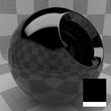
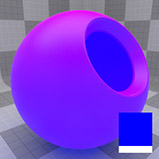
Reflection Color |
This option determines the tint on reflected light. By default the color is white, which reflects light without tint, so that at 100% Reflection Amount, anything reflected in the surface would appear as if you were seeing it in a mirror. Setting the Reflection Color to something other than white tints all reflected elements with that color. NOTE: The Reflection Color control is only visible with the Traditional and Energy Conserving shading models when the Reflection Amount is set above 0%. |
|||
|
|
|
|
|
|
|
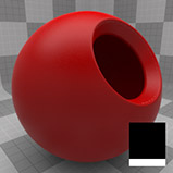
Reflection Type |
This control allows you to choose between Full Scene reflection evaluation or Environment Only. This setting effectively switches between ray traced reflections and an environment map technique. The Full Scene option is more accurate at the expense of greater render times. Environment Only utilizes only the settings in the Environment Item. |
|||
|
Blurry Reflection |
When enabled, Modo creates a blurred reflection with the blur intensity driven by the Roughness setting. It is important to understand that blurry reflections cause multiple reflection rays to be evaluated, and each ray is perturbed from the actual surface normal for every pixel. The higher the Roughness value the more reflection rays are required to reduce noise in the reflection. If you consider that when the Roughness value is increased, the angle of each ray also increases, you can imagine that the resulting sample from each ray can be quite different from one another. As such, a much higher number of Reflection Rays is required to get an accurate average sample. |
|||
|
|
|
|
|
|
| Roughness 0% | Roughness 25% | Roughness 50% | Roughness 75% | Roughness 100% |
|
Reflection Rays |
This value is only active when Blurry Reflections is enabled. Increasing the Reflection Rays amount improves the accuracy of the blurred reflection and reduces grain at the expense of computation time. Typically larger Roughness settings require larger Reflection Ray settings, because a wide spread of blur needs more samples to be accurate. If render times are a concern, you can decrease the Roughness value rather than simply increasing the number of rays. |
|||
|
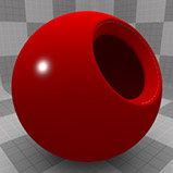
Clearcoat Amount |
This setting allows you to easily add an additional un-blurred and un-tinted reflective layer to a surface, simplifying the simulation of multiple layers of paint, which can be especially useful for automotive surfaces. Many metallic colors spread a wide colored highlight over the surface and yet, still exhibit a smooth reflective layer as a result of an additional transparent layer called a Clearcoat. Setting Clearcoat Amount to 0% effectively turns the function off, increasing values add the reflective effect. We recommend that, in most cases, you'll just want to leave this setting at 100%. |
|||
|
|
|
|
|
|
| Clearcoat Amount 0% | Clearcoat Amount 25% | Clearcoat Amount 50% | Clearcoat Amount 75% | Clearcoat Amount 100% |
|
Clearcoat Roughness |
This control blurs the reflection shading added by Clearcoat, working the same as the normal Roughness setting, but specific to just the Clearcoat for independent control. NOTE: The Clearcoat Amount must be above 0% to see any roughness changes. |
|||
|
|
|
|
|
|
| Roughness Amount 0% | Roughness Amount 25% | Roughness Amount 50% | Roughness Amount 75% | Roughness Amount 100% |
|
Clearcoat Bump |
This value can be defined to control to what degree the Clearcoat shading ignores any bump mapping that has been applied to the surface. |
|||
|
|
|
|
|
|
| Clearcoat Bump 0% | Clearcoat Bump 25% | Clearcoat Bump 50% | Clearcoat Bump 75% | Clearcoat Bump 100% |
|
Surface Normal |
||||
|
Bump Amplitude |
Bump maps are a means of creating high frequency details on a surface that would be difficult, if not impossible, to model. Bump mapping itself is a technique that modifies a ray's direction when shading a surface, giving the illusion that a surface has more detail than it actually does. Bump Amplitude allows a single control per material for modifying the amount of bump on a surface, defined as a measurement. The size defined is relative to the surfaces actual size. The actual bump details come from the texture layer(s) driving the effect with the Bump Amplitude setting acting as a multiplier to create the final result. Please see Shader Tree for information on adding layers and setting their effects. |
|||
|
|
|
|
|
|
| Bump Amplitude 0 mm | Bump Amplitude 25 mm | Bump Amplitude 50 mm | Bump Amplitude 75 mm | Bump Amplitude 100 mm |
|
Displacement Distance |
Similar to Bump maps, Displacement is a means to add detail to a surface that would be difficult, if not impossible to model otherwise. The maps themselves can be generated in Modo using the sculpting toolset, or in an external application such as ZBrush™ or Mudbox™; even procedural textures are useful as Displacement sources. The Displacement Distance setting determines the maximum range that vertices can be created, or moved away, from the original mesh surface during micro-polygon tessellation. With a value of 2 cm, no vertex can be displaced more than 2 cm away from the original surface. Depending on the mesh's scale, this value may need to be increased significantly. NOTE: When textures are applied to the displacement channel, should the combined texture value become greater than 100%, the resulting surface appears to be clipped. |
|||
|
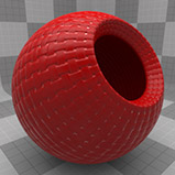
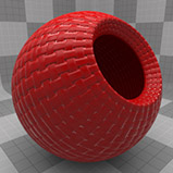
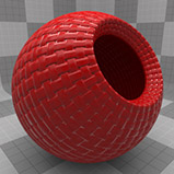
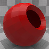
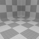
Smoothing |
Smoothing is a shading technique giving the illusion that geometry has more detail than it actually does. Without smoothing, geometric faces can appear faceted or flat. The Smoothing amount is set as a percentage, rather than a simple toggle, so that you have the flexibility to fade in the smoothing amount, or even drive it above 100% or below 0% to create interesting effects. TIP: At values over 100%, the smoothing effect results in pillowing around each polygon. |
|||
|
|
|
|
|
|
| Smoothing 0% | Smoothing 25% | Smoothing 50% | Smoothing 75% | Smoothing 100% |
|
Smoothing Angle |
This control determines which faces should receive smoothing. The Smoothing Angle sets a maximum angle tolerance between two polygons based on their normals. If the angle between the polygons is greater than the smoothing angle, no smoothing occurs. This is useful so that hard edges, such as cubes, are not smoothed across. The default value of 40° is a good general case value. |
|||
|
Double Sided |
When enabled, shading occurs from both sides of a polygon regardless of the normal direction. By default, this control is disabled so that polygons that do not face the camera seem invisible, as they only have one side. NOTE: In some cases Double Sided polygons can cause render errors with ray tracing of shadows and other effects. The Double Sided flag should be used sparingly, and never to correct poorly modeled meshes. |
|||
|
Rounded Edge Width |
The Rounded Edge Width option adjusts the rendered result of surface normals at a polygons edge to blend them with adjoining polygon normals, giving the impression of a small rounded edge between the two intersecting faces. You can define the width to determine the amount, or roundness, but keep in mind it is merely a shading trick and won't round the edges of the actual geometry, nor change the object's silhouette in the rendered image. Generally, it is best to set the width to just a few pixels in the final rendered image. |
|||
|
|
|
|
|
|
| Edge Width 0 mm | Edge Width 1 mm | Edge Width 2 mm | Edge Width 4 mm | Edge Width 8 mm |
|
Round Same Surface Only |
When enabled, edge rounding is constrained to the surface within the same item layer. When disabled, rounded edges are applied to the surface regardless of item layer. |
|||
|
Option |
Description |
|||
|---|---|---|---|---|
|
Layer |
||||
|
Enable |
Toggles the effect of the layer on and off, duplicating the functionality of toggling visibility in the Shader Tree. When disabled, the layer has no effect on the shading of the scene. However, disabled layers are saved with the scene and are persistent across Modo sessions. |
|||
|
Invert |
Inverts the RGB values for the layer producing a negative effect. |
|||
|
Blend Mode |
Affects blending between different layers of the same effect type, allowing you to stack several layers for different effects. For more on blending, see Layer Blend Modes. |
|||
|
Opacity |
Changes the transparency of the current layer. Reducing this value increasingly reveals lower layers in the Shader Tree if present, or dims the effect of the layer itself on the surface. |
|||
|
Transparency |
||||
|
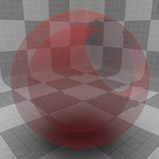
Transparency Amount |
The Transparency Amount controls how transparent or opaque a surface is. 0% is completely opaque and disables the setting altogether, settings above 0% gradually increase how transparent the surface is ramping toward 100%, which is completely transparent. |
|||
|
|
|
|
|
|
| Trans. Amount 0% | Trans. Amount 25% | Trans. Amount 50% | Trans. Amount 75% | Trans. Amount 100% |
|
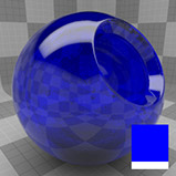
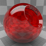
Transparency Color |
The Transparent Color determines what color a ray is tinted as it penetrates the transparent surface. Since many transparent materials, such as glass, should have no diffuse amount whatsoever, the transparent color is used for tinting the material. At the default, pure white, a material that is 100% transparent becomes completely invisible unless there are reflections and/or specular highlights. By changing the transparency color, the material becomes visible as Modo simply tints whatever the camera sees behind the surface. |
|||
|
|
|
|
|
|
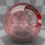
Absorption Distance |
Colored transparent surfaces don't often exhibit even coloration. Thin areas appear colorless while thicker areas are tinted with color. The Absorption Distance controls this effect, determining how far a ray must travel to get 100% of the Transparency Color. The falloff is determined by Beer's Law, just as in the real world. |
|||
|
|
|
|
|
| Absorption Dist. 100 mm | Absorption Dist. 200 mm | Absorption Dist. 300 mm | Absorption Dist. 400 mm | Absorption Dist. 500 mm |
|
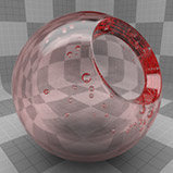
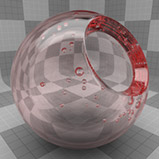
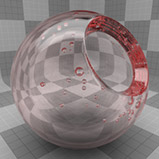
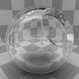
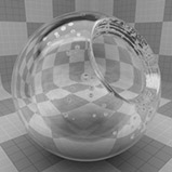
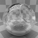
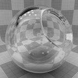
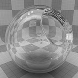
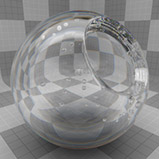
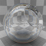
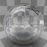
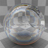
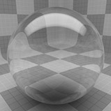
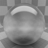
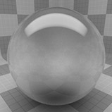
Refractive Index |
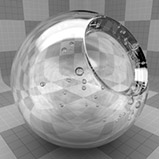
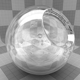
The Refractive Index determines how far a light ray is bent when it travels through a material and, when Use Refractive Index is enabled, the index determines the amount of surface specularity and reflectivity. The higher the value the more distorted the refractive/reflective items become. For example, a value of 1.0 is equivalent to light traveling through a vacuum and does not bend the rays at all. Increasing the value to 1.333 approximates the amount of distortion that occurs when light travels through water. NOTE: This setting requires that the surface has some amount of transparency active or that the Use Refractive Index option is enabled. |
|||
|
|
|
|
|
| Refractive Index 1.0 | Refractive Index 1.5 | Refractive Index 2.0 | Refractive Index 2.5 | Refractive Index 3.0 |
|
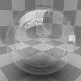
Dispersion |
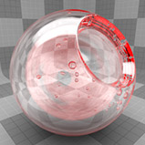
Dispersion is the difference of Refractive Index between various wavelengths of lights. Pure white light in the real world contains all colors of the spectrum as it passes through solid objects, and the refraction of different wavelengths varies creating a rainbow effect. You've likely witnessed this when shining a bright light through a prism. This effect in gemstones is usually referred to as 'fire'. In Modo, Dispersion is calculated as the difference between a high refractive index (at the violet end of the spectrum) and low refractive index (at the red end of the spectrum). A typical dispersion value for glass would be around .02 whereas diamond would be .044. Negative dispersion values invert to the usual curve. |
|||
|
|
|
|
|
| Dispersion 0 | Dispersion 0.025 | Dispersion 0.05 | Dispersion 0.075 | Dispersion 0.1 |
|
Refraction Roughness |
Some transparent surfaces are better described as translucent or cloudy. Light passes through the surface, but is diffused in such a way as to make opposing items blurry or even completely indistinguishable. Frosted glass exhibits this effect, items close to the surface are clear, but as they recede from view, edges and details soften increasingly. The Refraction Roughness calculates this effect by firing a number of jittered rays for each refraction ray and averages the result. A value of 0% disables the effect, whereas values above 0% increase the blurriness of items viewed through the surface. |
|||
|
|
|
|
|
| Ref. Roughness 0% | Ref. Roughness 5% | Ref. Roughness 10% | Ref. Roughness 15% | Ref. Roughness 20% |
|
Refraction Rays |
The Refraction Rays setting specifies the number of rays Modo uses to calculate the Refraction Roughness setting. As the roughness amount grows, the number of rays necessary to produce a smooth effect increases, at the expense of longer render times. |
|||
|
Dissolve Amount |
The Dissolve Amount allows you to fade an object completely from view, with a setting of 100% making the surface completely invisible. The Dissolve Amount is different from transparency, as it is a convenient way to fade all aspects of a surface simultaneously. |
|||

|
|
|
|
|
| Dissolve Amount 0% | Dissolve Amount 25% | Dissolve Amount 50% | Dissolve Amount 75% | Dissolve Amount 100% |
|
Subsurface Scattering |
||||
|
Subsurface scattering, or SSS, is the effect of light bouncing around inside a surface and being tinted prior to exiting. This is often most obvious in materials like marble, but is essential to creating realistic wax or fleshy materials. Subsurface scattering also helps simulated liquids such as milk to appear more natural. In humans, SSS is most often witnessed when thin areas on the ears seem to turn red from back light, because the light is being tinted by the tissue underneath the skin itself. |
||||
|
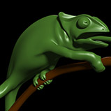
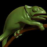
Subsurface Amount |
Subsurface scattering contributes to the diffuse shading of materials. The Subsurface Amount is a percentage value that determines the contribution of diffuse shading made by subsurface scattering. It is a good idea to keep this in mind in order to balance the percentages between Diffuse Color and Subsurface Amount depending on which effect you prefer for final shading. TIP: Combining high a Diffuse Amount and high Subsurface Amount can produce unnatural shading results. |
|||
|
|
|
|

|
| Subsurface Amount 0% | Subsurface Amount 25% | Subsurface Amount 50% | Subsurface Amount 75% | Subsurface Amount 100% |
|
Subsurface Color |
Subsurface Color is the color value that is used to tint the light as it is attenuated through the material. This setting and the Scattering Distance work together to determine how far the light must travel to be tinted. |
|||
|
|
|
|
|
|
Scattering Distance |
The Scattering Distance setting determines how far light must travel through the surface prior to exiting in order to be fully tinted by the Subsurface Color. If the light travels beyond the scattering distance it is further attenuated according to the original Subsurface Color. |
|||
|
Maximum Depth |
This option is a fast way to approximate an opaque solid core within the subsurface layer (such as a bone inside a finger) by clipping any scattering samples that reach beyond Maximum Depth value specified. This may lead to a slightly darker scattering because of the clipped samples exclusion from the solution, but an increase in the number of total Samples can help to reduce or eliminate this effect. A setting of zero disabled the option. |
|||
|
Front Weighting |
The Front Weighting value sets a bias for the SSS rays. At 50%, SSS rays scatter evenly forward and backward though a surface. Higher values bias the scattered rays toward the light source that emitted them, creating a more waxy/flat look to SSS. Values lower than 50% bias the scattered rays away from the light source, darkening the overall SSS effect. |
|||
|
|

|
|
|
| Front Weighting 0% | Front Weighting 25% | Front Weighting 50% | Front Weighting 75% | Front Weighting 100% |
|
Samples |
The subsurface Samples control the quality of the subsurface shading. Increasing this value improve the quality of the effect at the expense of render speed. The default setting is 64. |
|||
|
Same Surface Only |
When enabled, Modo's subsurface scattering works by limiting the SSS sample cache values to affect the shading to a single surface. This prevents certain artifacts that occur with very thin surfaces or intersections with non-SSS surfaces. NOTE: This optimization can stop adjoining SSS surfaces from sharing values, resulting in a slight dark border between them. If this occurs, disable Same Surface Only. |
|||
|
Luminosity |
||||
|
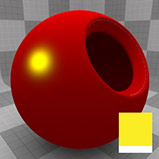
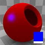
Luminous Intensity |
Luminous Intensity is multiplier that drives the brightness of the Luminous Color as it is emitted from the surface. This is different from the Diffuse Amount in that diffuse requires some amount of light to hit the surface, whereas luminous comes from the surface itself. It is accurate to think of luminous surfaces as light sources - particularly when using Global Illumination. The Luminous Intensity is multiplied to the Luminous Color. By default, the value is zero which results in the Luminous Color control being disabled. |
|||
|
|
|
|
|
| Luminous Intensity 0 | Luminous Intensity 0.25 | Luminous Intensity 0.5 | Luminous Intensity 0.75 | Luminous Intensity 1 |
|
Luminous Color |
This setting allows you to specify a color value for light emitted from a surface as specified by the Luminous Intensity setting. |
|||

|
|
|
|
|
|
Option |
Description |
|||
|---|---|---|---|---|
|
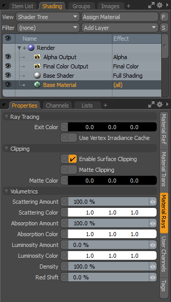
Ray Tracing |
||||
|
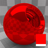
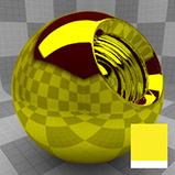
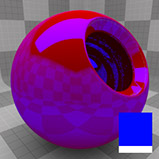
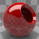
Exit Color |
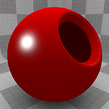
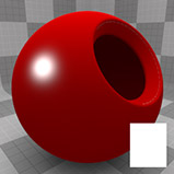
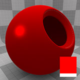
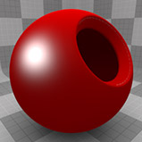
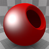
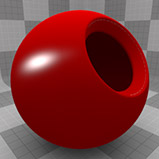
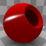
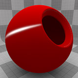
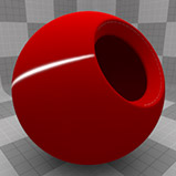
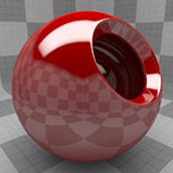
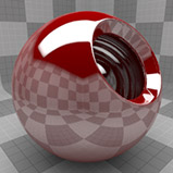
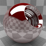
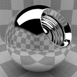
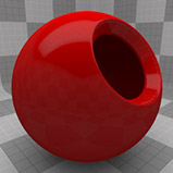
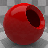
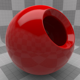
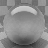
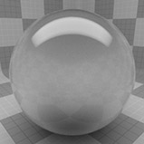
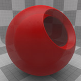
Originally, when a series of refraction rays hit the maximum refraction depth, Modo returned black as the final value, so scenes with low refraction depth values exhibited lots of dark areas. Exit Color allows you to specify the color Modo returns once it has reached its ray threshold. The color is still attenuated with the initial ray bounces (colors, absorption, and so on), however, this setting can reduce a lot of the dark areas present with lower refraction depth values. In the first example below, there is a good amount of black revealed because of the low refraction depth. In the second image, the exit color is changed to a medium gray, simulating the background color, which results in a more accurate representation. Finally, the last image changes the exit color to red making the effects of the Exit Color setting obvious. |
|||
|
|
|
|
||
| Exit Color (Default) | Exit Color Gray | Exit Color Red |
|
|
|
Use Vertex Irradiance Cache |
You can enable the Irradiance Cache to increase the performance of Irradiance Cache global illumination rendering for certain kinds of geometry, like characters and fur. This is because cached values are easily referenced, speeding up the evaluation of subsurface scattering, fur, and G.I. in general. When enabled on a surface, Irradiance Cache values are calculated at each vertex position (at the subdivision level) and interpolated in-between producing the shaded result. NOTE: The cache size is directly related to the subdivision vertex density, more polygons equals more IC values. |
|||
|
Clipping |
||||
|
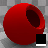
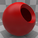
Enable Surface Clipping |
Enabled by default, Surface Clipping refers to the removal of part of the scene as defined by the Clipping Plane settings of the Camera Item. You can define a distance where all (or selected) surfaces are clipped, removing them from the rendered image while leaving the scene geometry intact. In order for Surface Clipping to work, it must first be enabled in the Camera item, under the Clipping attributes. You can define the distance value as well, determining the distance away from the camera where the scene clips the rendered image. You can disable the clipping effect on a per-material basis by disabling this option. TIP: A similar effect can also be obtained through the use of Render Booleans that are not camera view dependent. |
|||
|
Matte Clipping |
Matte Clipping provides a means to colorize interior areas of clipped geometry producing a filled area of color, the color being determined by the Matte Color value. |
|||
|
Matte Color |
Determines the color of clipped interior areas when Clipping is enabled in both the Material clipping attributes and in the Camera item. |
|||
|
Volumetric |
||||
|
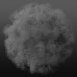
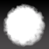
When light shines on certain matter suspended in the air, such as water vapor, smoke, dust, or even pollution, the particles become visible. This is known in computer graphics as a volumetric effect. Two things then happen to the light; part of it is bounced back in all directions (called scattering) and part of it is absorbed (called absorption). The Density parameter is the particle density of the volume, so the higher the density the more apparent particles there are. When the Density is increased, the scattering and the absorption increase as well, so your volume becomes both more opaque and more luminous. However, when Density is increased, the volume becomes more opaque and the light scattered inside is more attenuated, so the net result in terms of overall luminosity is hard to predict. The final result depends on the balance of scattering versus absorption versus density. In simple terms one can say that scattering is similar to diffuse shading and absorption is inversely similar to luminosity (more light reflected back makes the volume appear luminous). This is however more subtle than that since the overall luminosity also depends on how much absorption happens inside the volume. The following settings only apply to the volume item and otherwise have no affect on the surface. Likewise, the other surfacing attributes, such as Diffuse Color and Reflection Amount have no affect on a Volumetric item. The volume item also contains similar options that act as multiplies of the values below, allowing you some additional tweaking options. |
||||
|
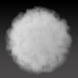
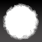
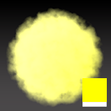
Scattering Amount |
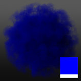
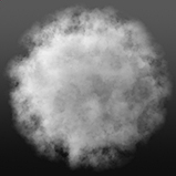
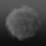
Scattering defines the amount of light that is reflected from the volume. This can also be described as how luminous the volume is, where a cloud is puffy and white, it is because it reflects back a lot of the light it receives (also absorbing very little). Conversely, a dense smoke cloud from an oil fire reflects back very little light, looking very dark and ominous. A value of 0% reflects back no light received from the source, up toward 100% (the default value) where the volume reflects back all of the light it receives. |
|||
|
|
|
|
|
|
| Scattering Amt. 0% | Scattering Amt. 25% | Scattering Amt. 50% | Scattering Amt. 75% | Scattering Amt. 100% |
|
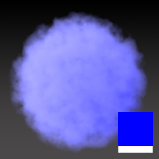
Scattering Color |
The Scattering Color represents the apparent color of the volume, representing the light that is reflected from the particulate matter. |
|||
|
|
|
|
|
|
|
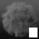
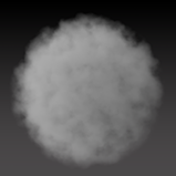
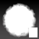
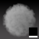
Absorption Amount |
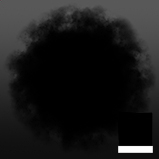
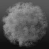
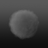
The Absorption Amount determines how much light is absorbed into the particular matter. If low amounts of light are absorbed, then more light is reflected back producing a brighter, more luminous volume. Where more light is absorbed, the volume appears darker, more powdery, and dust like. |
|||
|
|
|
|
|
|
| Absorption Amt. 0.01% | Absorption Amt. 25% | Absorption Amt. 50% | Absorption Amt. 75% | Absorption Amt. 100% |
|
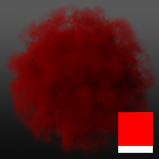
Absorption Color |
The Absorption Color determines the color that is absorbed into the volume (which produces an inverted hue to what is applied). |
|||
|
|
|
|
|
|
|
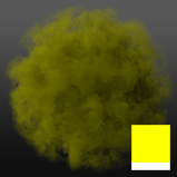
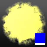
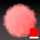
Luminosity Amount |
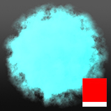
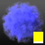
The Luminosity Amount when applied to a volume, gradually producing an overall, consistent coloration to the volume, as if it were a source of illumination. A value of 100% colors the entire volume the Luminosity Color value, flattening out the form, and eliminating any details. NOTE: The Luminosity level does not contribute any light to Global Illumination in a scene. |
|||
|
|
|
|
|
|
| Luminous Amount 0% | Luminous Amount 25% | Luminous Amount 50% | Luminous Amount 75% | Luminous Amount 100% |
|
Luminosity Color |
The Luminosity Color determines the coloration of the Luminosity Amount added to the volume. |
|||
|
|
|
|
|
|
|
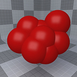
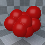
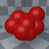
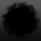
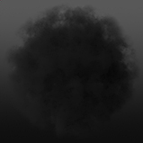
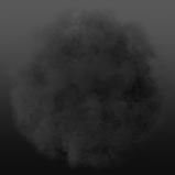
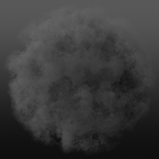
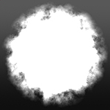
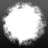
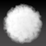
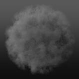
Density |
The Density value determines the thickness of the volume, controlling the apparent amount of particular matter that is visible. |
|||
|
|
|
|
|
|
| Density 100% | Density 75% | Density 50% | Density 25% | Density 0% |