Bezier Effector
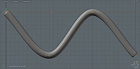
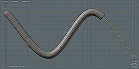
The Bezier Effector is an excellent way to apply deformations in a continuously smooth manner. Use Bezier Effectors for long tube-like structures (such as tentacles, tails, and whips). The Bezier Effector is functionally identical to the Spline Effector, but uses Bezier curve handles, which are somewhat easier to manipulate. You use the curve handles to control the line interpolation between anchor positions with additional handles. Doing this can provide for a more intuitive workflow.
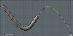
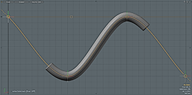
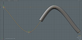
The Bezier Effector works as a group of Locators that define a Bezier-style curve through their collective locations. Their initial positions (defined as the Setup Position) determine the undeformed state of the target mesh, and as Modo moves each Locator, it calculates the difference from the unmodified curve and applies it to the mesh as the deformation. (This is why Curve Deformers always appear to have two curves associated with them.) As with many functions of Modo, there are several ways for you assign and apply a Bezier curve for deformations.
No Initial Curve
You don't need to create a Bezier curve prior to applying a Bezier Effector. Modo opens the Create Spline dialog box whenever you apply a Bezier Effector to a Mesh Item layer. The resulting curve aligns along one of the three axes in a straight line and centers on the specified axis. You either model the target geometry to match this requirement or enter Setup Mode after the fact and reposition the generated curve to coincide with appropriate locations relative to the geometry it's meant to deform.
To apply the Deformer itself, you first select the target Mesh Item layer either in the Items list or in the 3D viewport. With the target item selected, you then either click the Bezier button in the Deformers sub-tab in the Setup interface layout, or you right-click the target layer in the Items list and choose choose Item Operations > Add Mesh Operation, then under Effectors, double-click Bezier Effector.
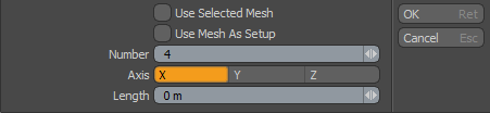
In the Create Spline dialog box, you only need to modify three values: Number, Axis, and Length. Number indicates the number of Bezier Node control points along the length of the curve. More control points provide finer control over the deformation, but they are also more difficult to deal with. Because the deformation smoothly attenuates between each location, you should define the minimum number of points necessary to obtain the desired effect. The Axis value indicates to Modo which axis it should use to generate the resulting spline. Length determines overall length of the resulting curve when centered at the World origin. Modo places the base of the generated curve on the negative side of the specified axis and draws it towards the positive direction. By clicking OK or pressing Enter, you save the values, and Modo generates the Bezier Effector and adds a number of Bezier Node items into the Item List as indicate with the Number value. These are the items that Modo manipulates in the scene to deform the target geometry.
If you need to make modifications, press the Setup button in the Setup interface layout to enter the Setup action state. In this state, you can modify the curve relative to the target geometry without generating any deformations. (This also temporarily disables any position changes applied to the curve outside of Setup.) When you properly position the curve, you can exit the Setup action state and change the positions of any of the Bezier Node items to deform the target mesh. To do this, select the Bezier Node item, itself, and move it with the transform tools. Set keyframes as necessary for a desired animation. To change the incoming and outgoing curve shape more intuitively, left-click the extended control handles on the Bezier node item.
User Created Curve
To create a custom Bezier curve to use as a Deformation controller, generate the curve in the same Item layer as the target mesh it's meant to deform. (You can also do this by cutting and pasting prior to invoking the add Bezier deformer command.) You can draw the spline with the Bezier tool.
Once you create the Bezier curve, you add it as a deformer to the mesh. To do so, you must be in the Polygons component mode with the target curve as the only curve selected. With the target Bezier curve selected, you can then either click the Bezier interface button in the Deformers sub-tab in the Setup interface layout, or you can right-click the target layer in the Items list and choose Add Mesh Operation, then under Effectors, double-click Bezier Effector.
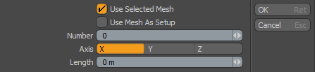
For a user-created curve, you only need to select Use Selected Mesh to have the tool use the selected curve. Everything else keys off the curve itself.
If you enable Use Mesh As Setup, Modo sets up the Bezier deformer so that it uses a curve polygon in the mesh to define the setup position for the deformer, then creates locators in appropriate places for the animated deformation.
After you click OK or press Enter, Modo accepts the values and generates the Bezier Deformer. Modo also adds a number of Bezier Node items into the Item List (based on the number of vertices in the specified Bezier curve). Modo uses the Bezier Node items to actually deform the target mesh. To have Modo do this, select the Bezier Node item itself, move it with the transform tools, and set keyframes as necessary for a desired animation. To change the incoming and outgoing curve shape more intuitively, left-click the extended control handles on the Bezier node item.
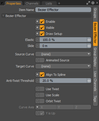
Bezier Effector Properties
To access the options related to the Bezier Effector, select the Bezier Effector item itself within the Groups Viewport as the parent of the Locators or in the Deformers palette and view the associated attributes in the Properties panel.
|
Bezier Effector |
|||||||
|---|---|---|---|---|---|---|---|
|
Enable |
Toggles the effect of the layer on or off. When clear, the layer has no influence on the scene. However, Modo saves disabled layers with the scene and their values are persistent across Modo sessions. |
||||||
|
Visible |
Toggles the visibility of the curve representations in the 3D viewport. |
||||||
|
Draw Setup |
Toggles display of the setup curve in the 3D viewport. |
||||||
|
Elastic |
Determines to what degree Modo deforms the item as Modo stretches it along the curve to match its overall length. A setting of 100% (the default) stretches the deformed area to the same length as the target curve. With a setting of 0%, the item retains its original undeformed length along the curve. Deforming always originates from the start of the curve itself. For items that are shorter than the target deformation curve, use the Slide option to position the item along the curve.
|
||||||
|
Slide |
Moves the target item along the length of the curve. Use this especially when the target item is shorter than the deforming curve. For example, use this to animate a snake along a predetermined path by setting the Elastic value to 0% and then using the Slide option to deform the snake along the curve.
|
||||||
|
Source Curve/Target Curve |
Provides an additional way for you to deform a target mesh using a custom-created curve that is itself deformed by another Deformer. (This bypasses the need to create handles for manipulating the curve.) First, create the curve and then duplicate the curve as a new item to have two identical versions in separate item layers. (Each item layer should have only a single curve.) Next, assign the deformation to the Target Curve. (For example, create a Morph for the curve.) Next, add a Spline Curve Deformer to an Item but do not indicate a specific curve to have Modo create the Effector. You can then specify the deforming curve as the Target Curve and the undeformed version as the Source Curve. |
||||||
|
Animated Source |
Indicates when you animate the Source Curve. When you select this, Modo constantly evaluates the Source Curve. If clear, Modo only evaluates the Source Curve's position on the first frame. Tip: When you see that a curve is reversed from what you expected, you can invert the point order by selecting the target curve in one of the component modes and pressing F. Now, what was the start is the end and vice versa. (This is the same action as flipping a polygon's normal face). |
||||||
|
Align To Spline |
When enabled, aligns the deformation of the points to the tangent of the spline. |
||||||
|
Anti-Twist Threshold |
Defines the size of the region on the curve where the rotation axis is interpolated. Tip: You can avoid using the Anti-Twist threshold when creating circles or loops, by making the setup spline perpendicular to the deformed curve. So for a deformed loop lying in the XZ plane, it works best if the setup curve is along the Y axis. |
||||||
|
Use Twist |
When enabled, uses the rotation of the control handles to twist points around the spline axis. |
||||||
|
Use Scale |
When enabled, uses the scale of the control handles to scale the points. |
||||||
|
Orbit Twist |
When enabled, adds twist to rotate the deformed spline node around the rest position. |
||||||
|
Curve Axis |
Determines how Modo uses the Locator transform channels. Select X, Y, or Z. Rotations along the selected axis add twist; Modo ignores the other rotation axes. Scaling perpendicular to the axis stretches the mesh perpendicular to the Curve Axis. |
||||||
|
Y is Up |
Sets where the twist occurs (the twist coordinates' zero-twist value) if you have selected Curve Axis. In certain cases, you may want to clear this option to avoid kinks in a deformed mesh when twisting. |
||||||
Bezier Node Item
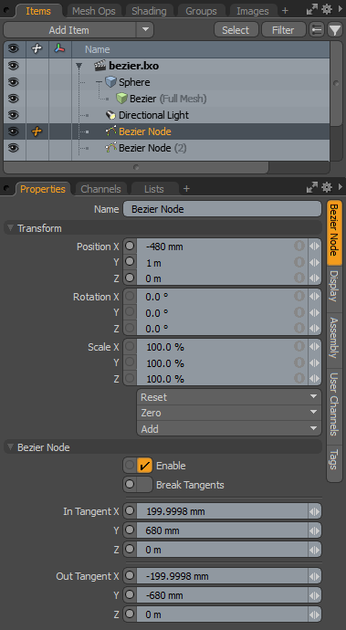
To control the deformation of the target geometry, you actually manipulate a Bezier Node item in the scene. Multiple nodes define a virtual Bezier curve that deforms the target mesh. Each Bezier Node has settings for its Position as well as the position of the control handles.
Use the Scale and Rotation values to modify the manipulator handles, but these do not influence the actual deformations of the target. The position of the Incoming and Outgoing Tangent control settings control the deformations. You set these values manually in the Item's Properties panel after you select the item, or you can left-click the item in the viewport and transform it directly. Moving the handles always moves two axes at once, and these axes always move relative to the current Work Plane position.
Name: Displays the current item's name. You may change the name by left-clicking the current name and typing a new name.
Transform
Position X/Y/Z: Define the location in 3D space for the Bezier Node. These positions relative to the other nodes defines the curve that Modo uses to deform the target mesh.
Rotation X/Y/Z: Have no influence over the deformations of the target mesh. Adjust the Tangent Handles instead to twist the incoming or outgoing angles of the Bezier curve.
Scale X/Y/Z: Have no influence over the deformations of the target mesh.
Reset: Resets the selected transform values to (0,0,0) and returns the items back to the World origin. As a deformer, resetting changes the location of the Bezier Node influencing the deformation of the target mesh unless you apply it to the items in the Setup action state.
Zero: Resets the selected transform property values to 0 and leaves the Center and Mesh positions intact. (Modo adds a negative transform item to the Mesh Item's Channels.)
Add: Adds a Transform item to control an item's position, rotation, or scale. By default, new items do not have any transform items associated with them (although they are visible within the Properties panel). Only add the necessary transforms on an as-needed basis to reduce scene overhead. You can also use this Add function to add a selected set of transforms to the Channel list while keeping the default 0,0,0 values, which is necessary for Referencing. (To override channels, they must exist.)
Bezier Node
Enable: Toggles the selected Bezier handle on and off for the deformation. When selected, the handle influences the deformation of the target mesh. When cleared, the handle's influence is ignored.
Break Tangents: If you select Break Tangents, Modo treats the handles independently of each other. Use this to create a corner or a sharply angled curve (joint). Bezier control handles are, by default, tangent (straight or linear) on opposing sides of the node position to produce a smooth curve across the Bezier node's position.
In Tangent X/Y/Z: Represent the X,Y, and Z position values of the Incoming Tangent handle relative to the actual position of the Bezier Node. To manipulate the curve's shape, you can manually enter locations or left-click the handles in the 3D viewport and adjust two axes simultaneously relative to the position of the Work Plane.
Out Tangent X/Y/Z: Represent the X,Y, and Z position values of the Outgoing Tangent handle relative to the actual position of the Bezier Node. To manipulate the curve's shape, you can manually enter locations or left-click the handles in the 3D viewport and adjust two axes simultaneously relative to the position of the Work Plane.