Display Preferences
You can fine-tune different aspects of Modo's displays.
To access these preferences:
• On Windows, open System > Preferences.
• On Mac OS, open Menu > Preferences.
3D Information Overlays
Each 3D viewport displays a variety of information as a HUD (heads-up display) directly in the viewport. You can control what information is viewed by these toggles.
|
Morph Map |
Displays the name of the currently selected morph map, if available. |
|
Current Selection |
Displays selected element information, based on the current mode (component, item or otherwise). |
|
Reference Item |
Displays the name of the source file for selected items that are part of a referenced scene. |
|
Selected Channel Count |
Displays the number of currently selected (active ) channels in the Channels Viewport, useful for keyframing. |
|
Deformers Enable State |
Displays the current state of deformers. Animated deformers can be enabled in the 3D (OpenGL) Viewport options. |
|
OpenGL Polygon Count |
Displays the number of GL polygons, including those added by Subdivision Surfaces. |
|
Grid Size |
Displays the real-world measurement equivalent of the current grid divisions. |
|
Active Passes and Actions |
Displays any active Passes and/or Actions by name that are selected. |
|
Polygon Type |
Indicator displays polygon type for active mesh layers: Face, Subdiv, Catmull-Clark or mixed. |
|
Current Tool |
Displays current tool information as well as info for falloffs, Action Centers and Snap. |
|
Snapping State |
Displays the current enabled options for Applying Snapping. |
|
UV Coverage |
Displays a percentage value in the lower-right corner of UV viewport, representing the amount of uniform UV space of the total region that is covered by geometry. When you use an UV editing tool, the coverage is updated editing and after releasing the mouse button.
Tip: This option is useful to game workflows when trying to maximize the amount of texture space being used for the target surface. |

Colors
You can customize the colors of many aspects of Modo related to the 3D Viewports (application-specific viewports don't have directly editable color schemes).
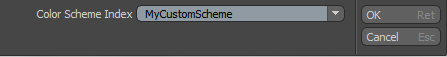
Note: Modifying colors in Preferences does not affect the actual default viewport colors. In order to apply a color scheme to a viewport, you first need to adjust the colors in this section, then use the Save to Scheme function and assign a new name using this dialog box.
Once a scheme name has been set, you need to switch back to the particular 3D viewport you wish to apply the scheme to. Presets can be applied to each viewport separately, determined by its Active status. Active viewports are separated by the Thumb changing to an orange color. You can activate any viewport by simply clicking anywhere over the viewport window. Next, click View > Viewport Color Scheme, then select the previously saved scheme from the list. The following elements of Modo can be customized.
OpenGL
|
Texture Resolution |
This value (set as powers of 2) determines the largest bitmap texture size displayable in Modo 3D viewports before Modo resorts to mipmapping, which is a method of subsequent resamples of an image at a lower resolution that enable faster image drawing to the 3D viewport. Higher settings increase image quality, but require greater video RAM. |
|
Environment Resolution |
This value specifies (in pixels) the maximum image resolution for environment images. Unlike Texture Resolution, this option is used only for Environment lighting. The default setting is 4096 x 2048. The following resolutions are supported: • 64 x 32 • 128 x 64 • 256 x 128 • 512 x 256 • 1024 x 512 • 2048 x 1024 • 4096 x 2048 • 8192 x 4096 • 16k x 8192 Tip: Suggested system requirements: |
|
Flatness of Perspective |
This option determines the amount of perspective in the 3D perspective viewport. Similar to the Field of View option in the Camera options panel. The higher the value, the flatter the perspective; the lower the value the more distorted and extreme the perspective becomes. |
|
Max GL Polygon Count |
This option defines an upper limit to the number of polygons visible in a 3D viewport. It triggers an error message allowing you to cancel the previous operation if it were to exceed the defined amount. This option was created mostly to help you avoid locking up a system when trying to subdivide a model too many times when using multiresolution sculpting. |
|
Bounding Box Threshold |
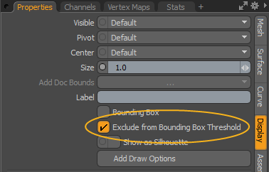
This option draws items as bounding boxes when rotating, panning, or zooming in the viewport, if the Open GL polygon count exceeds the Max GL Polygon Count value. This eliminates lag and makes it easier to work with large scenes. You can enable this option for All Surface Items, or Only Inactive Surface Items. You can also exclude individual items by enabling Exclude from Bounding Box Threshold in the Display tab of the item Properties. For more information, see Display Viewport.
Tip: For a short video on this option, see Related Videos. |
|
Bounding Box Drawing in Animation |
Only available when Bounding Box Threshold is not None. When enabled, surface items with a polygon count exceeding the Max GL Polygon Count value are displayed as bounding boxes during animation playback and when scrubbing the timeline. |
|
Enable Displacement in GL |
This option determines if displacement effects are displayed in the GL viewports as actual polygon displacement. When disabled, displacement displays in the 3D Viewports as a bump map. |
|
Grid Visibility |
This option determines the default visibility state of the ground plane grid visible in 3D Viewports. It is enabled (visible) by default. |
|
OpenGL Point Size |
This option determines the size of the on-screen display of vertices, specified in screen pixels. The default value is 3. Consequently, it also controls the selection hit area for selecting vertices. |
|
Selected Point Size |
To make it easier to see their on-screen display, selected vertices can be displayed larger in the 3D viewport, an amount determined by this option. Scale is based on the original OpenGL Point Size option. |
|
Viewport Fit Factor |
You can automatically frame the view of all the elements of a scene to the bounds of the active viewport by using the menu bar commands View > Fit All or View > Fit Selected (or keyboard equivalents A or Shift+A, respectively). This option determines the scaling of the fit. 1 corresponds to 100%, fitting the bounding box of the elements to that of the viewport's shortest length. The default of 1.5 provides a little room around the elements and ensures that the viewport fits into view regardless of bounding box size. |
|
Topology Vertex Backface Culling |
When enabled, this option disables the display of vertices for rear facing polygons while using the Topo display mode. This makes distinguishing foreground vertices easier when editing. |
|
Weight Value Precision |
If a Weight Map and vertices are selected with the Show Weight Values option enabled, the Weight Value Precision option determines the number of decimal places shown for the weight values in the GL viewport. |
|
Transparency |
|
|
Selection |
When viewing a selection through an opaque surface, this option determines the opacity of the selection highlighting through the surface (similarly to an X-ray). This is especially helpful in differentiating front and rear facing selections. |
|
Handles |
When viewing tool handles through an opaque surface, this option determines the opacity of the handle itself, making it possible to see the handles through the surface. |
|
Topology Polygons |
This option determines the transparency of forward-facing polygons while in the Topo display mode. |
|
Selection |
|
|
Selection Rollovers |
Pre-highlighting of elements in a scene helps you to make selections, showing which elements are getting selected when the mouse button is clicked. The Selection Rollover option determines how the highlighting occurs. • None - No pre-highlighting of elements in the scene. • Manual - Pre-highlighting of elements is based on the current mode (vertices, edges, polygons, items, and so on). • Closest - Pre-highlighting the nearest geometric component element regardless of mode. |
|
Mouse Regions Trigger Selections |
With this option enabled, you can automatically switch between component modes (vertex, edge, polygon) by right-clicking the target element. Tip: Combine this with the selection rollover set to Closest to aid determining the proper element to click on. |
|
Performance |
|
|
VBO Mode |
VBO stands for Vertex Buffer Object, a method of working and displaying geometry in OpenGL. VBOs offer substantial performance gains over the older immediate mode rendering method, but may also cause problems with older graphics cards, or graphics cards with lacking drivers). Modo tries to determine the best mode when set to Auto, depending on the video cards driver. You can also manually enable/disable the option with the On/Off options to increase stability. |
|
Only Draw Selected Procedural Outlines |
When this option is enabled, Modo only draws the surface outline for procedural geometry (such as the Gear Item). When disabled, Modo draws any individual triangles that make up the surface. |
|
Sync Display Refresh |
Also know n as Vsync. When enabled, this option helps with tearing in the GL viewports but may cause lag with larger meshes and lower framerates. |
|
Sync Application Response |
When enabled, this option syncs the application with the 3D OpenGL viewports reducing lag, but it can sometime also significantly reduce the 3D Viewports framerate, dependent on the scene's contents. |
|
AVP Allow Material Texture storage |
Controls how the 3D Viewport stores its data internally in the textures or uniform buffers. When disabled, Modo reduces the maximum size of the scene displayed and the framerate is higher to improve performance. Note: In order for your changes to take effect, you must restart your computer. |
|
Performs Color Correction on OpenGL Objects |
This option toggles the color management of the 3D Viewports. When enabled, the 3D Viewports are adjusted using the current Color Management settings. When disabled, the viewports are not corrected. Note: In complex scenes, corrected viewports may reduce display performance. |
|
Backdrop Item |
|
|
Include Backdrops in Viewport Fitting |
When using the Viewport Fit Factor function of a viewport, enabling the Include Backdrops option accounts for the size of any visible backdrop item when calculating bounding box size for the fit action. |
|
Display Backdrops in Uniform Size |
When this option is enabled, backdrop items ignore image size, and base the scale of the backdrop on the item's Scale value. |
|
Pixel Size |
When importing bitmap images for use as backdrops, this option determines the measurement of a single pixel in an image upon import, allowing you to place backdrop images scaled to real world size. For example, if Pixel Size is set at 10 mm, a 512x512 image is imported at 5.12 meters in size. |
|
Item Drawing |
|
|
Default Size for New Scenes |
Determines the default drawing size in the 3D Viewports for non-Mesh Items, such as cameras and lights. You can also adjust the scaling values manually in the Display viewport. |
|
Default Size for Current Scene |
Determines the default drawing size in the 3D Viewports for non-Mesh Items added after a scene is created. You can also adjust the scaling values manually in the Display viewport. |
|
Schematic |
|
|
Schematic Grid Snapping |
Specifies the grid size for node snapping in the Schematic. The default value is 2.0. A value of 0.5 produces the pre-Modo 11 behavior. |
RayGL
|
Resolution |
When RayGL in-viewport render preview is utilized, this option determines the resolution of the rendered image, initially based on the on-screen size of the 3D viewport. Lower resolutions update more quickly. There are three options: • Full - Renders at the same pixel resolution of the viewport. • Half - Renders at half the resolution of the viewport. • Quarter - Renders at one quarter of the resolution of the viewport. |
|
Updates |
This setting determines the way the RayGL preview updates (or renders) while working in a 3D viewport. Three options are available. • Delayed - This option updates the viewport preview when the mouse button or tool handle is released. • Lazy - This option updates the viewport each time a pause is encountered, regardless of mouse or tool state. • Synchronous - This option continuously updates the viewport, as best as the system is able to process the data, reducing resolution as necessary to keep up. |
|
Quality |
When RayGL in-viewport render preview is utilized, this option determines the quality of the rendered display. • Draft - Renders the image using a reduced number of ray samples, as specified in the Render preferences, in the Preview section under Preview Draft Quality Settings. This option produces a faster, though less accurate result. • Final Render - Renders the image using the same number of rays you specify for the final render. • Extended Refinement Passes - Renders the image with additional ray samples beyond any value specified for IC, MC, Reflections, Refractions, Transparency and Subsurface Scattering up to the number of rays specified within the Render preferences section, under Preview. |
|
RayGL Toggles |
For memory or calculation intensive scenes, you can disable certain effects from being considered in RayGL processing. The various options can be toggled independently: shadows, reflections, refractions, global illumination, displacements, fur and low fur density. You can also reduce the polygon count of fur texture layers without disabling fur entirely. |
|
Draft Quality Settings |
|
|
When using a preview viewport with the Quality settings in the RayGL section set to Draft, the following options determine the quality settings solely for the preview viewport itself. You can throttle material and render setting values for more responsive preview performance. |
|
|
Displacement Rate Multiplier |
Sets the maximum displacement rate for Micro Polygon displacement. |
|
Quality |
Sets the preview quality as a percentage. At 50%, all Samples, Number of Rays and other related quality setting are cut in half reducing rendering quality, but increasing performance. |
|
Antialiasing Samples |
Sets the maximum amount of antialiasing samples calculated for the preview. |
|
Max GI Bounces |
A general quality settings multipliers that throttles the total number of rays related to IC, transparency, reflections and refractions. The default setting of 50% reduces the total number of rays specified by half. |
|
Max MC Rays |
This option determines the maximum number of Monte Carlo global illumination rays used to calculate indirect lighting. |
|
Max IC Rays |
This option determines the maximum number of Irradiance Cache rays used to calculate indirect lighting. |
Tool Handles
|
Large/Small Points |
Determines the visible size, in pixels, of manipulator handles displayed on tools, such as those on the Curve drawing tools. |
|
Large/Small Points Hit Size |
Determines the hit area where a mouse click affects the particular tool handle. Typically, this value is larger than the handle size, to make it easier to select a particular handle, but making it too large can make it difficult to select a specific handle in a tight cluster. |
|
Handle Line Width |
Determines the width, in pixels, of the lines drawn for tool handles, such as the widgets for Move, Rotate and Scale. |
|
Handle Line Hit Width |
Determines the hit area where a mouse click affects the particular tool handle. Typically this value is larger than the handle size to make it easier to select a particular handle. |
|
Handle Scale |
|
|
Standard |
If your screen is very large or very small, you may prefer to set the default size of the tool handles larger or smaller using this setting. Handles stay consistent in size regardless of viewport scaling. You can also interactively Scale tool handles by pressing the - and = keys. |
|
Small (% of Standard) |
Some tools have a smaller secondary handle. You can adjust its size here based on a percentage of the Standard amount. |
|
Plane Handle Ratio |
Many tools have additional plane handles, that constrain actions to two axes simultaneously. You can adjust the plane tool handle sizes based on the Standard amount. |
|
Draw Style |
|
|
Selected Tool Handles |
Determines the default drawing behavior for tool handles. The following options are available: • Invisible - No handles display in the viewport. • Basic - Basic tool handles display allowing you to constrain certain functions when used, based on the particular tool. • Advanced - Additional controls or handles appear, where available, to aid in setting certain options for a tool or item. For example, when selecting the Camera item with any tool that has advanced handles, additional controls become visible for setting Focal Distance and F-Stop. |
|
Unselected Tool Handles |
Depending on the tool, additional handles display in the viewport, especially those related to setting falloff positions and sizes. The Unselected Tool Handles option determines the drawing options for these types of additional handles. |
|
Auto-Haul Display |
Some tools can be enhanced with additional on-screen controls. For example, advanced in-viewport sliders can specify Bevel Shift and Inset. This option determines whether or not to draw such additional helpers. • Off - Disables display of additional on-screen tool auto-haul displays. • Basic - Displays only basic tool handles. • Advanced - Displays only advanced tool handles when available. • On - Displays on-screen auto-haul handles defaulting the settings of the preset itself as determined by its options in the Tool Pipe. |
|
Handle Snapping |
|
|
These are the default values, in pixels, for the distance from a snapping target where the cursor first gets snapped. |
|
|
Inner Range (pixels) |
Determines the actual snapping range. |
|
Outer Range (pixels) |
Determines the range to highlighting elements for snapping to. |
|
Rotation Snap Angle |
Sets the angle of the fixed intervals for any rotation tools. Activated only when pressing Ctrl before rotating the target element. |
Related Videos
Bounding Box Threshold
Courtesy William Vaughan