UV Mapping
Vertex Maps are a special type of vertex-specific information stored within a mesh’s vertices, such as color (RGBA Maps), position offsets (Morph Maps) and percentages (Weight Maps).
A UV Map is a type of vertex map that stores vertical and horizontal positions on a 2D texture. The letters U (Horizontal) and V (Vertical) denote the axes of the 2D texture because X, Y and Z are used to denote the axes of the 3D space.
This video takes a quick look at UV mapping in Modo.
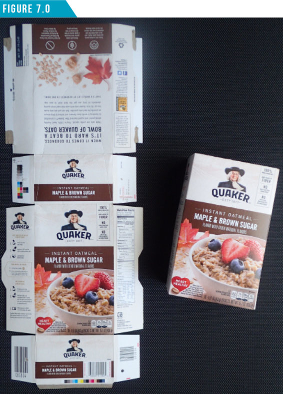
UV Mapping is the process of translating a 3D surface with volume and shape onto a flat 2D texture image. One way to visualize how this works is to think of cutting open product packaging and laying it flat as seen in (Figure 7.0).
Modo provides a special viewport along with a collection of tools and functions, which work in conjunction to simplify the otherwise tedious process of UV mapping.
I’ve included a scene file that contains two mesh items: a UV’d character mesh and a simple coil mesh without UVs. You’re free to use them if you’d like to follow along.
Download the MODO Essentials.zip from the Course Files tab here: https://learn.foundry.com/course/3128/view/modo-essentials
Open (File/Open) the source file Modo_Essentials/Source/S7/Scenes/MagmaToad_ Vaughan.lxo
With the scene loaded, let’s prepare the workspace. Use the Viewport Switcher Pie Menu (Alt+Spacebar) to open the Left Viewport. By default the Left Viewport will be set to the UV Viewport, but if it’s not, simply change it using the UV icon (second from left) that is located just above the Left Viewport.
Next, switch to the UV Toolbar using the second icon from the left in the Toolbar Menu. Your workspace should look like (Figure 7.1).
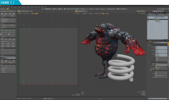
This is an ideal layout for working with UVs. It gives you quick access to the UV Viewport, 3D Viewport and all the UV tools. Let’s take a look at the UVs that are already created for the MagmaToad mesh item.
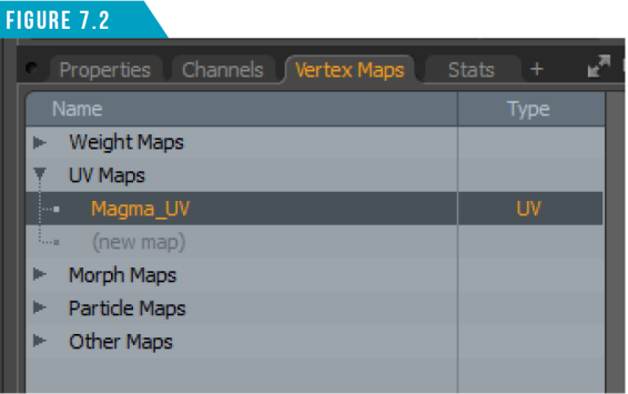
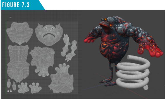
Select him in the Items List, open the Vertex Maps Tab, click the small arrow (►) next to UV Maps, and then select Magma_UV (Figure 7.2).
The Left Viewport should now display the selected UV Maps’ UVs. (Figure 7.3)
As we discovered in Explore the Modo User Interface, anytime you see a small gear icon in the top corner of a viewport, it denotes viewport options. The UV Viewport has its own set of specific options for changing the display settings.
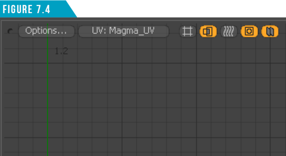
In the top-left section of the UV Viewport, you’ll find some quick access buttons (Figure 7.4). These buttons are similar to the ones found in the 3D Viewport, but these focus on display options related to UVs.
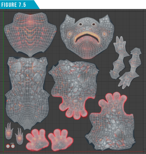
From the UV Viewport Options Popup, choose (Backdrop/ToadMagma). This will display the image that is applied to the MagmaToad surface in the UV Viewport (Figure 7.5).
Speaking of tweaking UVs, although it’s great that Modo offers an amazing array of UV specific tools, it’s good to know that you can use the standard tools and falloffs to manipulate UVs as well.
For example, I use Element Move pretty much every time I’m UV mapping, and when UV mapping character faces, I almost always use Radial Falloff with the Scale tool to help fix UV distortion.
Let’s create UVs for the Coil mesh item to get an idea of creating UVs from scratch. Start by turning off the backdrop image display (Options/Backdrop/None).
Select the Coil mesh item, and then use the selection skills you learned in Section 2 to mimic the selection seen in (Figure 7.6). You should be able to select the edges in three steps.
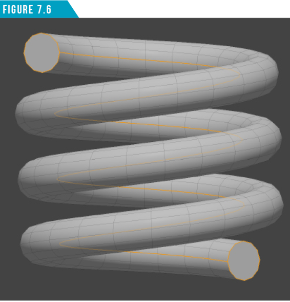
We’ll use this edge selection to define our UV seams. UV Seams are the areas of the mesh that are cut to allow the 3D mesh to be flattened. It is usually best to place seams where they are the least visible, so I chose to select the edge loop that is on the inside of the coil.
With the edges that will define our UV seams selected, create a new UV Map by selecting (New Map) in the Vertex Maps Viewport. Give the new map a unique name (Coil_UV) and click OK.
Activate the Unwrap Tool located at the top of the UV Toolbar and then left-click and drag in the UV Viewport until your UVs look like (Figure 7.7).
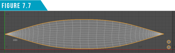
Drop the Unwrap Tool (Q). While technically unwrapped, these UVs are not ideal. There is some major distortion in the main portion of the coil’s UVs.
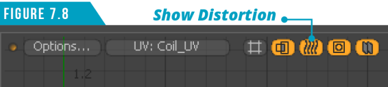
If you’d like a visual display of distortion, click the (Show Distortion) icon in the top-left portion of the UV Viewport (Figure7.8).
Distortion is a fact of life with UV mapping, and completely eliminating distortion is not always required. My end goal is to produce UV maps with as little distortion as possible. This visual display helps show where distortion is happening.
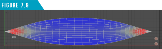
Polygons that are the closest in relative size to others in the map with the least distortion display a middle gray/green color.
Distorted and smaller relative polygons fade toward red; distorted and larger relative polygons display as blue.
Looking at the UVs in our coil (Figure 7.9), it becomes obvious we have a distortion issue we should address.
There are many options for manipulating the UVs and addressing distortion. As mentioned earlier, we have access to all the tools in the UV Toolbar as well as the standard modeling tools in the Model Toolbar.
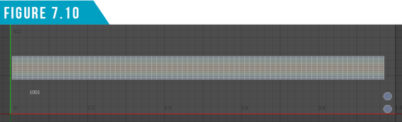
Since the shape of this UV island is a rectangle, we can take advantage of a powerful command in the UV Toolbar called (Rectangle), which straightens quadrangle selections of UVs into rectangle sections.
Change to Polygon Selection Mode, doubleclick on the UV island that makes up the main part of the coil to select all of the connected polygons, and then run the Rectangle Command from the UV Toolbar. Your UVs should now have little to no distortion and they should look like (Figure 7.10).
One look at the UV Toolbar and it becomes obvious that we’ve only just scratched the surface of UV mapping in Modo. Spend some time exploring the UV Viewport options as well as the collection of UV specific tools available in the UV Toolbar.
|
||
|
Load up the Gidget and Pepperjack and Crunk Car scenes and have a go at UV’ing them. Start with some of the smaller, simpler components and then work your way to some of the more complex organic shapes. Play with UV seam placement and explore some of the UV specific tools to see how they can aid in the UV mapping process. |