The Light, Point, DirectLight, and Spotlight nodes all have controls that you can use to adjust how the lights cast shadows in your 3D scene. The following geometry nodes also have controls that allow you to select whether they receive shadows cast by the lights and whether they themselves cast shadows on other objects:
• Card
• Cube
• Cylinder
• Sphere
• MergeGeo
• ModelBuilder
• PointCloudGenerator
• PositionToPoints
• ReadGeo
• Scene
Note that the method used to create shadows varies between different render nodes:
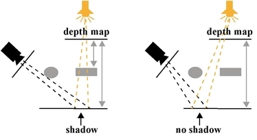
• ScanlineRender uses depth mapping to create shadows. It first renders a depth map for each light that casts a shadow. The depth map is rendered from the light’s point of view, and each pixel in the depth map represents the distance from the light to the nearest surface the light illuminates in a specific direction. The depth map is then compared to the render from the point of view of the camera. If a point is farther away in the image that the camera sees than in the depth map, then that point is considered to be in shadow.
Depth map shadows are often faster to render than raytraced shadows, but may not appear as realistic.
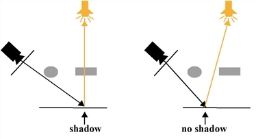
• PrmanRender creates shadows through raytracing. It fires individual light rays from the camera into the scene for each pixel. When a light ray hits a surface in the scene, PrmanRender traces so called shadow rays between the intersection point and every light source in the scene. If there are obstacles between the intersection point and the light sources, the intersection point is considered to be in shadow.
The advantage of raytracing is that it can be used to create more accurate shadows and shadows that have soft edges, much like those in the real world. However, compared to creating shadows using depth mapping, raytracing can take much longer to render.
| 1. | Open the properties panels for the 3D objects in your scene. |
| 2. | Check the cast shadow or receive shadow box, or both. |
Cast shadow tells objects in a light’s path to cast shadows onto other objects in the scene.
Receive shadow tells objects to display shadows cast by other objects in the scene. This is useful for showing occlusion in a scene.
You can also use a Scene node to define these settings for all 3D objects connected to it. In the Scene properties, set shadow to override inputs and use the cast shadow and receive shadow controls to override the corresponding controls on the individual 3D objects.
| 3. | Make sure you’ve got a Shader node attached to any 3D objects that you want to receive shadows. |
| 4. | Attach a light to your scene, and check the cast shadows box on the Shadows tab. |
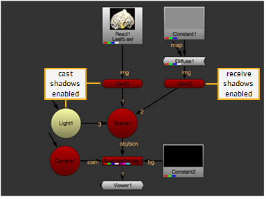
In our example node tree below, we are using a ScanlineRender node, but you could use a PrmanRender node instead.
NOTE: If you are using a point light, casting shadows is not supported in the ScanlineRender node.
| 5. | Depending on the render node you are using, proceed to either: |
• Adjusting Shadows When Using ScanlineRender below, or
• Adjusting Shadows When Using PrmanRender.
| 1. | On the Shadows tab of the light node properties, set shadow mode to: |
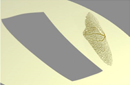
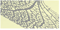
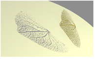
• solid - Objects seen from the light that cast shadows are considered completely solid.
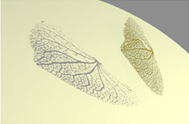
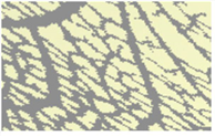
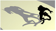
• clipped alpha - objects that cast shadows are considered to be transparent if the object’s alpha is below the light’s clipping threshold control. All other alpha values fully occlude the light.
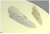
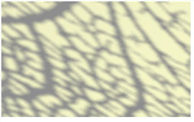
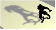
• full alpha - Shadows are calculated based on how light is reduced when it passes through non-opaque occluders.
This affects shadows cast by objects, based on the objects’ opacity.
|
|
|
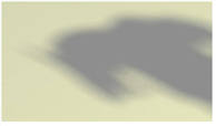
| Solid. (The shadow is rectangular because the leaf image is applied on a Card object.) |
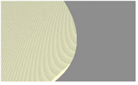
Clipped alpha. |
|
|
| Full alpha. |
| 2. | If you want the light node to to output the shadow map, set output mask to the channel where you want to store this. You can enable this even if cast shadows is disabled. |
| 3. | If you set shadow mode to solid or clipped alpha, you can adjust the following: |
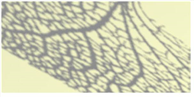
• depthmap resolution - this sets the resolution of the depth map. Larger values result in shadows with less crunchy edges and less artifacts, but require more time to process.
|
|
|
| Depthmap resolution set to 800. |
Depthmap resolution set to 7400. |
Note that you can also fix crunchy edges by increasing the number of samples instead of increasing the depth map resolution.
• samples - this sets the number of samples for the light when generating soft shadows. If soft shadows in your scene appear dotty or noisy, try increasing this value. The higher the value, the smoother the soft the shadows become.
|
|
|
| Samples set to 1. | Samples set to 50. |
• jitter scale - the amount of jitter used when doing percentage-closer filtering (PCF) for soft shadows. A larger jitter scale value results in softer, more perceptually accurate shadows.
PCF works by sampling the depth map at many different positions around the same spot. The final shadow value for that spot is an average of how many of the samples were occluded or visible from point of view of the light.
• bias - this is a constant offset that moves the surface sample point away from surface, towards the light that is casting the shadow. If self-shadowing artifacts appear in the image, you may want to increase this value. Note, however, that if you increase the value too much, some shadows may start moving away from the base of the objects that cast them.
|
|
|
| Shadow artifacts. | Increasing bias can help reduce artifacts. |
• slope bias - this is like bias, but the offset is proportional to the slope of the depth map. This allows you to give a different offset to each value in the depth map, depending on the surface’s slope relative to the light. For example, if the surface’s slope relative to the light is shallow, the value in the depth map may be a correct approximation and no offset (or only a very small offset) is needed. If the surface’s slope relative to the light is steep, the values in the depth map are less likely to be a correct approximation and a larger offset is needed.
If increasing bias reduced the existing self-shadowing artifacts but introduced more artifacts in other areas of the image, you may want to bring bias down a little and increase slope bias instead. Then, tweak both values until you’re happy with the result.
In the clipped alpha mode, you can also adjust:
• filter - the type of filter to use. For more information on the available filtering algorithms, see Choosing a Filtering Algorithm.
• clipping threshold - any surface samples with alpha values below this threshold are considered transparent. The higher the value, the more areas on objects that cast shadows are considered transparent and pass through some light.
|
|
|
| Clipping threshold set to 0.1. | Clipping threshold set to 0.9. |
| 4. | If you set shadow mode to full alpha, you can adjust the following: |
• filter - the type of filter to use. For more information on the available filtering algorithms, see Choosing a Filtering Algorithm.
• scene epsilon - an offset that moves the sampling point away from the geometry surface, towards the light that is casting the shadow. Increasing this value can reduce self-shadowing artifacts.
TIP: To generate accurate shadows from a Direct light, view the scene through the light (using the Viewer's camera dropdown menu) and adjust the Direct light's scale control so that the part of the scene that should cast shadows fits within the view. This ensures that none of the shadow-casting geometry is missed by the depth map.
| 1. | Open the PrmanRender properties and make sure shadows is enabled. |
| 2. | Open the light node properties and go to the Shadows tab. |
| 3. | Make sure shadow mode is set to solid. The other two modes aren’t relevant when using PrmanRender. |
| 4. | If you want to cast soft shadows from the light, increase sample width. This value multiplies the width of the soft area around the egde of a shadow. The higher the value, the larger the soft area. |
|
|
|
| Sample width set to 1. | Sample width set to 15. |
| 5. | If you increased sample width in the previous step and the resulting soft shadows in your scene appear dotty or noisy, increase samples. This sets the number of samples for the light when generating soft shadows. The higher the value, the smoother the soft shadows become. |
|
|
|
| Samples set to 10. | Samples set to 80. |
| 6. | If self-shadowing artifacts appear in the image, increase the bias value. This moves the surface sample point away from surface. Note, however, that if you increase the value too much, some shadows may start moving away from the base of the objects that cast them. |
|
|
|
| Shadow artifacts. | Increaseing bias can help reduce artifacts. |