geometry.
With the DisplaceGeo node, you can modify geometry based on an image. When using the node, each vertex is displaced along its normal with a value corresponding to the image pixel the vertex’s uv attribute points to. The higher the pixel value, the greater the displacement.
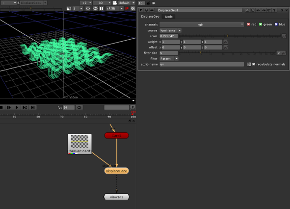
The following image illustrates the principle behind the DisplaceGeo node. A Card node is modified to resemble the pattern of a Checkerboard image.
|
|
| Using the DisplaceGeo node to modify geometry. |
| 1. | Select 3D > Modify > DisplaceGeo to insert a DisplaceGeo node anywhere after the 3D object you want to modify. |
| 2. | Attach a Viewer to the node to see your changes. |
| 3. | In the node’s controls, use the display dropdown menu to select how you want to view your object in the Viewer while making changes to it. |
| 4. | Read in your image map and connect it to the DisplaceGeo node’s displace input. |
| 5. | Adjust the following controls: |
• From the channels dropdown menu and check boxes, select the channels to use for the displacement value.
• From the source dropdown menu, select the source for the displace value. For example, if you selected rgb or rgba from the channels dropdown menu, you can use the red, green, blue, or alpha channel or the pixel luminance as the source. You can also select rgb relative to move the vertices on the x, y, and z axes by the amounts in rgb, or rgb absolute to move the vertices to the values in rgb.
• To define the scale of the displacement, adjust the scale slider. The higher the value, the bigger the displacement.
• To give x, y, and z different weightings, enter new weights the weight fields. By default, each weighting is set to 1. If you don’t want to make changes to a value, set its weight to 0.
• To offset x, y, and z values, enter the value by which you want to offset them in the offset fields. For example, if you enter 0.5 in the y offset field, 0.5 is added to the y value.
• To change the size of the filtering applied to the image before the displacement, adjust the filter size slider.
• To select the filtering algorithm applied to the image before the displacement, select an algorithm from the filter dropdown menu. For more information, see Choosing a Filtering Algorithm.
• To change the name of the attribute that’s used as the vertex’s UV coordinates to find the image pixel, enter a name in the attrib name field.
• Usually, the normals aren’t correct after the vertices have been moved. To recalculate them after the displacement, check recalculate normals.