Morphing
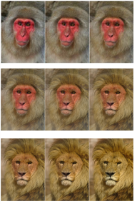
Morphing refers to dissolving two images together so that the subject of one image seems to change shape and turn into the subject of the other through a seamless transition. A morph can be easily noticeable or very subtle. An example of a noticeable morph would be a man turning into a woman or one animal turning into another, whereas a transition from an actor to his stunt man would result in a much more subtle morph.
|
|
An image of a monkey turning
into an image of a lion. |
Morphing can be a time-consuming task, but it can be made easier by good advance planning of the shots. The more similar the characteristics, position, and movement of the subjects you want to morph are, the easier it is to morph them together. If the position and the movement of the subjects do not match, however, you can try to reposition and retime the clips before morphing them together. To do so, use the nodes described in Transforming Elements and Temporal Operations. You can also use the Tracker and PlanarTracker nodes to track the features you want to morph over time or to stabilize your clips before morphing them together. See Transforming Warps for more information.
Below, we first discuss morphing images using the GridWarp node and then using the SplineWarp node.
Morphing One Image into Another Using the GridWarp Node
To morph one image into another using the GridWarp node:
|
1.
|
Select Image > Read to import the two images you want to morph together. |
|
3.
|
Select Transform > GridWarp to insert a GridWarp node into your script. |
|
4.
|
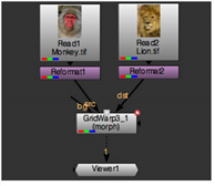
Connect the source image (the image you want to turn into another image) to the src input of the GridWarp node, and the destination image (the image you want the source image turned into) to the dst input. Connect a Viewer to the GridWarp node. |
|
5.
|
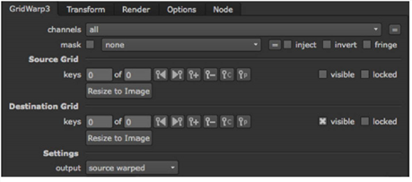
To make the grids the same size as the input images, click the Resize to Image buttons under both Source Grid and Destination Grid. |
|
6.
|
In the GridWarp Settings controls, set output to source to display the source image and grid. |
|
7.
|
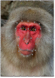
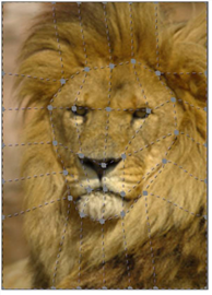
Adjust the grid to follow key features on the source image. For example, if you’re morphing an animal, you might consider the eyes, nose and mouth. |
|
8.
|
In the GridWarp Settings controls, set output to destination to display the destination image and grid. |
Note: If the source and destination images are similar, you can copy the source grid onto the destination grid using the copy and paste  buttons.
|
9.
|
Adjust the grid to follow key features on the destination image. |
|
10.
|
In the GridWarp Settings controls, set output to morph to display both grids and activate the warp and mix sliders. |
|
11.
|
Scrub to the frame where you want the morph to begin. Bring the warp slider down to 0 (the source image). Click on the animation button  and select Set key. Then, scrub to the frame where you want the morph to end and set warp to 1 (the destination image). and select Set key. Then, scrub to the frame where you want the morph to end and set warp to 1 (the destination image). |
|
12.
|
Animate the mix control in the same way. Scrub to the frame where the morph starts, and set mix to 0 (the source image). Click the animation button and select Set key. Scrub to the frame where the morph ends, and enter 1 (the destination image) as the mix value. |
Play through the sequence in the Viewer and you’ll see that the source image is morphed into the destination image.
Morphing One Image into Another Using the SplineWarp Node
To morph one image into another using the SplineWarp node:
|
1.
|
Select Image > Read to import the two images you want to morph together. |
|
3.
|
Select Transform > SplineWarp to insert a SplineWarp node into your script. |
|
4.
|
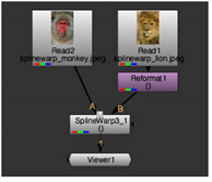
Connect the source image (the image you want to turn into another image) to the A input of the SplineWarp node, and the destination image (the image you want the source image turned into) to the B input. Attach a Viewer to the SplineWarp node. |
|
5.
|
In the SplineWarp node’s controls, switch output between A and B or click  and and  in the Viewer tools. You should see both images in the Viewer. in the Viewer tools. You should see both images in the Viewer. |
|
6.
|
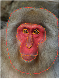
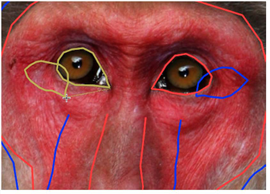
Identify some features that are similar in the source and the destination images. For example, if you are morphing together images of people or animals, these features might include their eyes, noses and mouths as well as the outlines of their faces and heads. |
You may find it useful to name the entries in the curves list, left_eye, right_eye, etc. Meaningful names can help you later on when you’re using the Join tool to link the source and destination shapes.
|
8.
|
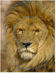
Switch to input B and draw curves in a similar fashion. Draw the same amount of curves, on similar features, to make the morph as accurate as possible. |
|
9.
|
Switch the Viewer to output ABmorph  , which displays both sets of curves, and activate Join , which displays both sets of curves, and activate Join in the Viewer tools. in the Viewer tools. |
|
10.
|
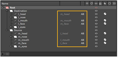
Work through the A input shapes, linking them to their B input counterparts. Try to link similar points, such as the corners of the eyes or the side of the mouth. |
Note: You can invert the source and destination shapes using the Reverse tool.
As you join shapes, the curves list updates showing the linked pairs.
|
11.
|
Scrub to the frame where you want the morph to begin. Bring the mix slider down to 0 (input A). Click on the animation button and select Set key. |
|
12.
|
Set keyframes for root warp in the same way. |
|
13.
|
If you’re using stills, as in this example, scrub the playhead to the number of frames required for the morph. Otherwise, scrub to the end of the sequence. |
|
14.
|
Set the mix and root warp sliders to 1 (input B). |
|
15.
|
Press Q in the Viewer to disable the spline overlay and press play. |
Input A is morphed into input B.
Using the cookie-cutter to create traveling masks
The curves list cookie-cutter is primarily designed to overlay a morph between two images, which may not include an alpha channel, on top of a sequence by creating a “traveling mask” automatically between closed cookie-cutter shapes.
For example, the monkey-lion morph demonstrated previously could be merged with a sequence, replacing a face with a monkey face that is morphed into a lion over time.
Note: The cookie-cutter only works with closed shapes from the curves list.
|
1.
|
Designate a pair of closed shapes as cookie-cutters by clicking the cookie-cutter icon in the curves list. |
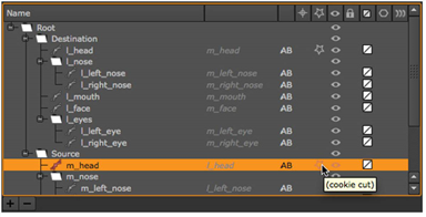
In this instance, enabling cookie-cut for the monkey’s head, m_head, also designates the lion’s head, l_head, as a cookie-cutter shape.
|
2.
|
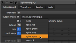
Use the output mask dropdown to select the channel where the traveling mask is stored, or use the mask_splinewarp.a default. |
|
4.
|
Finally, merge the output of the SplineWarp node with your sequence. A simple script might appear as follows: |
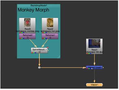
You can confirm the presence of the traveling mask by selecting the output mask channel in the Viewer dropdown and then pressing M to display the Mat channel. You should see an automatically created mask that matches the morphed shape.