2D Architecture
NUKE’s 2D architecture is largely defined by the Iop class. This class inherits from Op, reimplementing _validate(), and extending functionality to add an image processing path. In turn, Iop is extended and specialized by PixelIop and DrawIop to provide simplified implementations for specific classes of image processing operator.
Iop specifically defines how NUKE’s channel system works, how regions of interest and regions of definition are passed up and down the tree, how 2D data is cached, and how bounding boxes and image formats are dealt with.
Scanline-Based
NUKE is a non-destructive, node-based, 32-bit float, multi-channel, scanline image compositing system. You can think of the purpose of NUKE as consuming input images, performing image modification operations on them, and then producing output images. In addition to the scanline-based 2D image system there are also a number of sub-systems available, such as the 3D system, Deep Image compositing system, and Particle system. In general, these sub-systems do not operate on 2D images. However, their output mostly gets converted into a 2D image at some stage so that NUKE can produce a final 2D output image. For instance, the 3D system gets converted into a 2D image by the ScanlineRender node at which stage the 3D image becomes part of the scanline based image system.
This section covers the fundamentals of the scanline render system to give you an overview on how NUKE works. It does not cover the other sub-systems in detail, although many of the concepts are shared with the other sub-systems.
A Basic Node Graph
Imagine a simple image processing graph (usually called Node Graph or DAG) in NUKE, consisting of three nodes. The first is a CheckerBoard, the second a ColorCorrect, the third a Viewer node.
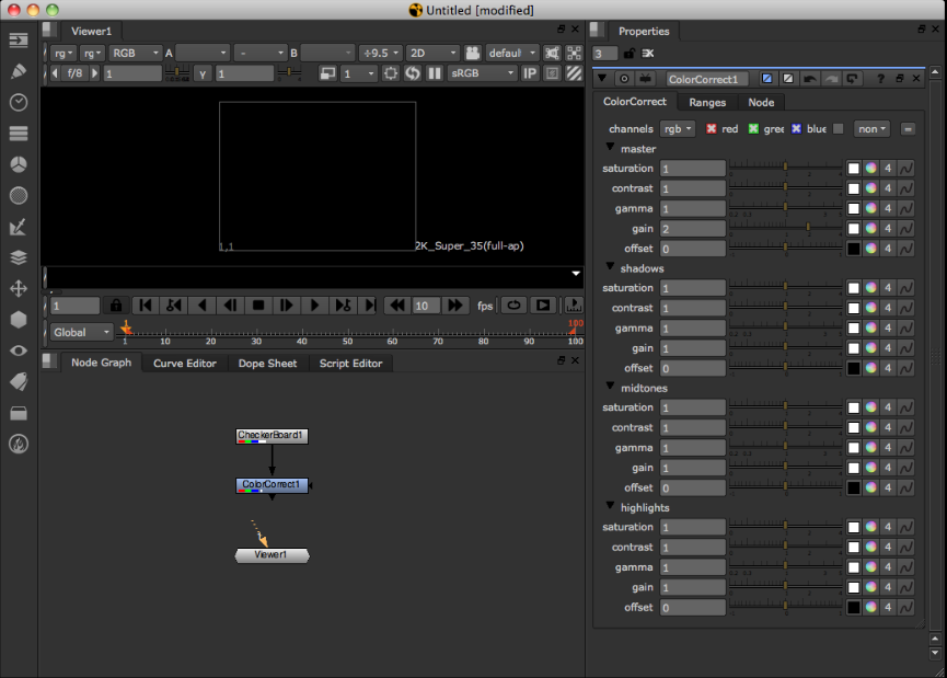
You can think of these three nodes as representing the fundamental three types of node in NUKE: 1. a generator or input node (CheckerBoard) 2. a filter or modifier node (the ColorCorrect) 3. an output node (the Viewer).
At this stage in the NUKE Viewer there is no image present. That is because the Viewer node is not connected to the Node Graph.
Because there is no image present, no image processing or image loading has occurred.
The only time image processing occurs is when an output node asks its input nodes for an image. This is known as a ‘pull’ system.
An output node can be considered the bottom node in the graph that is going to produce output on either the screen (a Viewer) or written out to disk (a Write node).
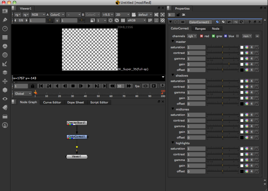
In the screenshot above the user has connected the Viewer to the ColorCorrect node.
At this stage the Viewer node needs to produce an output picture. In order to produce an image, it asks its input node (the ColorCorrect) for an image. The ColorCorrect also now needs to produce an image. Again, it needs to ask its input (the CheckerBoard) for an image. The CheckerBoard, having no inputs and being a generator of images, does’t need to ask its inputs, so it just returns an image to the ColorCorrect, which in turn modifies the image and returns it to the Viewer, and the processing tree is complete.
Fundamental Image Processing Unit - the Row
As described earlier, NUKE is a scan-line based system. This means that according to NUKE the fundamental unit for image processing is a scan-line. The scan-line is one horizontal line of the image. In the NDK a scan-line is known as a Row.
NUKE always operates on the level of Rows when processing images. Knowing this then, our processing of an image in our simple three-node tree looks something like this:
- The Viewer needs to display an image of 640x480 resolution.
- It splits the image up into 480 Rows.
- It asks its input, the ColorCorrect, for a Row at a time.
- The ColorCorrect asks its input for a Row at a time.
- The CheckerBoard generates a Row at a time and returns it to the ColorCorrect.
- The ColorCorrect modifies each Row and returns it to the Viewer.
This architecture is the main reason NUKE can deal with almost unlimited image sizes. Because image processing is limited to Row-size chunks, the whole image does not need to reside in the computer memory at once.
The Viewer and Large Image Sizes
When displaying a large image on the Viewer screen, there are typically less Rows displayed on the screen then actual Rows in the full image. For instance, an image that is 4k or 3112 Rows high can be displayed on the screen in a box that is 800 Rows high. When this occurs, the Viewer does not ask its input for every Row to produce the output image, as they are not required for display on the screen. In other words, the Viewer skips Rows.
- The Viewer needs to display an image of 4k resolution in a 800-pixel high box.
- It splits the image up into Rows and asks its input for these Rows, skipping ones it doesn’t need. For example, Row 0, 4, 8, 12, 16, and so on.
- For each Row (0, 4, 8, 12, 16, and so on), the ColorCorrect asks its input for a Row (0, 4, 8, 12, 16, and so on).
- The CheckerBoard generates the required Rows (0, 4, 8, 12, 16, and so on).
This is one of the reasons NUKE is fast and interactive even when dealing with large image sizes.
This strategy for dealing with large image sizes also means that Rows are always computed at full resolution horizontally. Once they are computed, they are correct no matter what the zoom level on the image in the Viewer. In other words when the user zooms in, the Viewer only needs to ask its inputs for Rows it hasn’t asked for yet.
Multi-Threading
When producing the output image, the output node typically runs multiple threads to fetch multiple Rows from its input at the same time.
For instance, on a four-core system the Viewer launches four threads to each independently process a Row of input at time. This can be seen in the NUKE user interface as two white lines: one is the top-most thread processing a Row, and the other the bottom-most thread. The threads are scheduled in a very simple first-come, first-served manner.
For instance, when processing a 480-Row image with no line skipping, the Viewer typically runs the first four threads working on Rows 0 to 3. As each thread finishes, it is given the next available Row to work on until the whole image is complete.
In general, a processing operation does not create its own threads for processing, but is run on one of the output node processing threads as it is asked to generate a Row. NUKE has internal synchronization that guarantees only one thread is operating on one Row of one node at a time.
The Row Cache
Typically when doing image processing, when some nodes are asked to produce their Row of output, they actually need more than one Row of input to produce the output Row.
For instance, a Box Blur may need many input Rows for each output Row.
For example, imagine we added a Blur node after the ColorCorrect in our three-node tree. In this case, for each Row of output for the Blur node, there is an overlap of Rows that are required from the ColorCorrect. In other words, the Blur node asks for some Rows in the ColorCorrect multiple times.
In order to avoid computing the same Rows multiple times, NUKE generally creates a cache for those Rows. In this case, the first time a Row is required from ColorCorrect, that Row is copied into a cache. The next time the Blur node asks for the same Row, it is returned from the cache instead of being computed again.
The Row cache is described in the NUKE user interface as the ‘image buffers’. It can be cleared by pressing F12, and its maximum memory size can be set in the Preferences. The Row cache is a memory buffer - it is generally not written to disk so therefore it does not survive between runs of NUKE.
Note
There is one node that actually writes the Row cache to disk. This is called the DiskCache node. It writes to disk or reads from disk any Rows that are required from it.
Tiles
Often when performing image calculations, your image processing engine needs to access more than just one Row from its input to produce its output Row. In order to do that, NUKE has a concept of a Tile.
A Tile has accessor functions on it that allow you to access pixels as a 2-dimensional array of the given Tile size.
It is important to note that the fundamental unit of image processing in NUKE is still a Row. When a Tile is created for an input Op, a cache is created (if one doesn’t exist already), and then NUKE fills the Rows required on that input Op to fill the Tile. Those Rows are then locked in the NUKE cache for the existence of the Tile object. You can then use accessor functions on the Tile into the internal Rows in the cache for that input.
This also means that when you have multiple threads all creating Tiles that overlap, quite often when the Tile is created many of the Rows are already in the cache for that Tile and only minimal extra processing occurs.
Channels
NUKE handles image colors as colors planes which are known in NUKE as channels.
Channels describe one floating-point component of all pixels in an image. A typical channel would be Red. Channel data is stored packed into arrays of 32-bit float, describing the value of that channel for every pixel in a Row.
Multiple channels make a channel set (sometimes called a layer). A channel set assigns meaning to the channels in it. For example, the predifined rgb channel set contains the channels r, g, and b, so operators can know that b is the blue channel of the rgb channel set.
Most often you access channels in NUKE by using the special macro ‘foreach’. This macro loops through a channel set, giving you each channel.
foreach( channel, channelSet ) {
  float *outputPixel = row.writable(channel);
}
The above example loops through all the channels in a channel set and then gets the output pixel pointer for each channel.
The Viewer Cache
It is worth mentioning here that there is another cache in NUKE in addition to the Row cache. This is called the Viewer cache and is also described in the Preferences and the user interface as the disk cache. The Viewer cache is a file written to disk for each frame as it is displayed in the Viewer. The Viewer cache file is NOT used for image processing and is separate to the Row cache. Its primary purpose is the quick display of images in the Viewer for playback and viewing. Because it’s written to disk, it survives between runs of NUKE.
When the Viewer as an output node needs to produce an output image for display, it first checks to see if any Rows that it needs to display are already in the Viewer cache on disk. If they are, it simply displays them rather than asks its input for the Rows. If any Rows are missing from the cache, the Viewer asks its input for them as usual.
Memory
When the Row cache memory size exceeds the limit set in the Preferences, NUKE searches the Row cache and frees as many Rows as required to get under the memory limit (plus around 10% for headroom). Typically, the algorithm used to decide on which Rows get freed first is a combination of request count, Row access count, and op ‘slowness’. Any Rows that are ‘locked’ by having an interest or Tile on them cannot be freed by NUKE.
Any user plug-in that needs to allocate its own temporary buffers must make sure they allocate and register themselves for out-of-memory conditions with the DDImage::Memory functions.
Note
Other items apart from Rows may also contribute to memory usage and trigger a memory free event. For instance, 3D geometry and any user-allocated memory registered with DDImage.
Iop Call Order
Construction, knob handling, and destruction of Iops is inherited directly from the Op class, as introduced in the Fundamental Concepts chapter, and discussed in detail in the Architecture section.
_validate
- void Iop::_validate(bool None)
As described in the Architecture chapter, validation consists of both Op level common functionality and sub-class dependant functionality. In the case of Iop and its children, _validate is responsible for setting up “IopInfo”.
The IopInfo contains various fields:
- IopInfo is a sub-class of the Box class. This is a simple bounding box and represents the area in which the Op has pixels, including any overscan that is available. This is displayed in the Viewer as the bounding box (or bbox).
- Two formats: one is the “fullSizeFormat”, and one is the regular “format”. In non-proxy mode these are the same, but in proxy mode the original, unscaled format is stored in “fullSizeFormat”, and the effective format as used by proxying is stored in “format”. The format is the region to which the bounding box is clipped when displayed in the Viewer.
- channels - These are the channels for which pixel data is defined. Attempts to fetch channels from Iops that do not have these channels result in zeroes.
- first_frame/last_frame - These represent the frame range for which the Iop is defined. For example, a Read node fills these in to the temporal range of the source material it is pointed at.
- black_outside - By default NUKE edge-extends Iops when you attempt to access them outside their bounding box. This is not always desirable, so Ops can set ‘black_outside’. This is slightly confusing in that rather than changing the default extension behavior, it instead means that the pixel data has been padded with an extra layer of black pixels (and the bbox padded similarly), and therefore for use of the bbox as numbers it will strip out that extra padding.
- ydirection - This indicates the preferred y access order. A negative value indicates that the preferred access order is from the top (high y) to the bottom (low y). A positive value indicates that the preferred access order is the other way round.
_validate is called on the main thread. It should avoid doing excessive calculations, as it will block the UI during its call. In particular, it should avoid calculating the image on the input, as this can take arbitrarily long.
The Iop has another field that can be set in _validate(), namely “out_channels_”. This defaults to Mask_All and has no effect. If it’s set to something smaller, then NUKE can, as an optimization, skip calling _request and engine() on this Iop entirely, and go straight to its input Iop (by default input(0), but this can be changed by setting raw_channels_from). This is not guaranteed, and implementations of engine() should still be able to deal with being called for channels not in out_channels_.
During _validate you can assume that the Op has been built for the right frame and view. outputContext() is valid and the knobs have been stored via knobs().
_request
- void Iop::_request(int x, int y, int r, int t, ChannelMask None, int count)
_request() is called by NUKE on your Iop to indicate the region and channels of interest. In turn your Iop should indicate the region and channels of interest by calling request() on its inputs as appropriate. It is important where possible to keep the region of interest down to the minimum necessary, as NUKE potentially calculates and caches the full region of interest.
In a complex tree, NUKE might call _request on your Iop multiple times - each time it passes the cumulative region and channels of interest.
_request() is usually handled in the main (UI) thread, and, like _validate(), should avoid taking too long.
The parameter count is a hint to the caching, and indicates how many overlapping requests have been made. When calling request() on your inputs, you can specify a value greater than one to force it to cache the data on this input.
The default implementation of _request() provided by Iop assumes that the inputs are derived from Iop. If you plan on having inputs that do not satisfy this (a GeoOp-derived input for example) then you must provide your own implementation of _reqest(). Without this, Nuke’s behaviour will be undefined.
open
- void Iop::_open()
_open is called immediately prior to the first engine() call on an Iop, after it has been _request()ed. Like engine(), it is called on a worker thread, and therefore can take any amount of time without causing the UI to block excessively. Calls to _open() are locked so that only one will happen, and this will be complete by the time other calls to engine() begin.
Unlike validate/request/engine, _open does not need to and should not recursively call its inputs.
engine (/pixel_engine/draw_engine)
- void Iop::engine(int y, int l, int r, ChannelMask channels, Row& row)
The engine function is responsible for actually operating on the image data. The engine type called depends on the Iop type, with engine() relevant to Iops, pixel_engine() relevant to PixelIops and draw_engine() to DrawIops. In this section we’ll explicitly discuss engine(), however the topics covered are relevant to all Iop derived classes and their engine methods.
engine() is called by NUKE on your Iop as the function that actually processes image data. This is called on the worker threads, and therefore should be thread-safe against itself and not make a large number of calls. In general, it should not call functions on knobs, particularly those that set or get values, as these calls are not thread-safe and may result in crashing. Any calculations based on knob values it requires should have already taken place in _validate, and result in fields within the Iop being set that engine() can later refer to.
It is passed in coordinates representing a segment of a scanline, and a set of channels and a Row is passed by reference. It is supposed to set up the Row so that all the channels are defined in the range x ... r. This value will have been set previously.
A trivial implementation of engine is as follows:
void engine(int, int, int, ChannelMask channels, Row& row) {
  row.erase(channels);
}
This blanks all the channels. Blanking must be done explicitly, as the state of Row is not defined to be empty initially. Another example that fills in all the pixels with the value 1 is as follows:
void engine(int y, int l, int r, ChannelMask channels, Row& row) {
  foreach(z, channels)
  {
        float* out = row.writable(z);
     for (int x = l ; x < r ; x++)
     {
         out[x] = 1.0f;
     }
   }
 }
We see here the use of writable(Channel), which obtains a pointer to the Row’s internal buffer for that channel, which the calling code can write into. writable(Channel) is based so that it is valid between the left and right extents of the Row (specified in its constructor, which has been run by the code that calls engine). It is not always valid to simply deference writable(Channel), as x may be higher than 0.
engine() can also fetch data from the input. For example, a simple passthrough operator would have this engine:
void engine(int y, int l, int r, ChannelMask channels, Row& row) {
   row.get(input0(), y, l, r, channels);
}
If it is possible to write your operator as a simple in-place modification of its input, we recommend doing so, as this leads to more efficient memory use. For example, a simple gain would end up being:
void engine(int y, int l, int r, ChannelMask channels, Row& row) {
  row.get(input0(), y, l, r, channels);
  foreach (z, channels)
  {
    if (z == Chan_Red || z == Chan_Blue || z == Chan_Green) {
        float* out = row.writable(z);
      for (int x = l ; x < r ; x++)
      {
        out[x] *= _gain;  // _gain here holds the value of a gain knob
      }
    }
  }
}
For more details about how to fetch image data in engine, please see Iop: Spatial Operators. Various sub-classes of and helper classes for Iop also exist that are there primarily to remove boilerplate within engine and add extra functionality.
close
- void Iop::_close()
_close is called some time after rendering has finished (for the moment). This cannot be relied upon to always happen when rendering finishes.
If NUKE decides that it needs to do more work, it will re-call open(). Unlike validate/request/engine, _close does not need to, and should not, recursively call its inputs.
Call Safety
All the functions above are called on the main or UI thread except the engine call and open call, which are called from worker threads.
You must ensure that any call on the main thread executes as quickly as possible to prevent any unwanted delays in the user interface.
Calls such as validate, request, invalidate, and UI or knob functions cannot be called from the engine call or a worker thread. Doing so is not thread safe and results in instabilty.
- In general, the following can be used from within an engine call:
- The Row class
- The Interest class
- The Tile class
- The Pixel class
- ChannelSet and other channel functions
- Calling the progress op functions
- Calling error, or warning on an op.
Formats & Bounding Boxes: RODs & ROIs
As a side-effect, _validate() produces the region of definition (in pixel coordinates) for an Iop, and places it into the IopInfo.
It should also produce two formats: the “full size format” (ignoring any downrez/proxy) and the “format” (which takes into account any downrez/proxy).
A simple implementation that just copies the (sole) input’s IopInfo is as follows:
void _validate(bool forReal)
{
   copy_info(0);
}
The default implementation also calls merge_info() to merge in the bboxes and channels of the other inputs.
NUKE then will call _request to indicate the region of interest. This should call request() on all its inputs as necessary, with that Op’s region of interest on those inputs. For example, a blur might wish to implement this like so:
void _request(int x, int y, int r, int t, ChannelMask channels, int count)
{
  input(0)->request(x - _size[0], y - _size[1], r + _size[0], t + _size[1], channels, count);
}
NUKE clips the regions in its implementation of request() that forwards to the plug-in’s function _request(), so that you never see a request that is larger than your bbox as you specify in _validate(), and you can happily request larger boxes than your info bboxes.
Coordinate System
NUKE coordinate system is internally pixel-based with 0,0 being the lower left. Support for non-one pixel aspect ratios and proxy-scaling/downrezzing exist and are generally transparent, with the user seeing coordinates that are properly canonical coordinates, but the code generally seeing pixel coordinates.
The pixel aspect ratio is a property of the image format rather than the data itself. When the knobs are being stored, NUKE takes into account the pixel aspect ratio for certain types of knobs. For example, suppose there is a Blur node, which has a “size” parameter, as follows:
float size[2];

Blur() {
  _size[0] = _size[1] = 10;
}

void knobs(Knob_Callback f) {
  WH_knob(f, _size, "size");
}
With square pixels and without being in any proxy mode, the size will end up being set to (10,10). If the pixels are twice the width they are high, then to achieve a blur that appears the same vertically as horizontally, we should only blur by half the number of pixels horizontally as we are doing vertically. Therefore, the call to WH_Knob() takes the value of input_format().pixel_aspect() into account in this case, and would result in _size being set to (5, 10) rather than (10, 10).
Proxy scaling is handled in a similar manner, except that proxy scales are passed in through the OutputContext (going from the bottom upwards, rather than coming from the top downwards like pixel aspect ratios). In this example, if the OutputContext() was set to downrez by 2, then _size would end up being (5, 5). The effect is multiplicative, so that if the pixel aspect ratio is 2:1 in addition to the downrez being 2, then _size would be (2.5, 5).
This sort of automatic downrezzing happens with the knobs() call on certain knobs: those dealing with 2D space. These are:
- BBox_knob
- Transform2d_knob
- WH_Knob
- XY_knob
It is possible to turn this off on a per-knob basis by setting the NO_PROXYSCALE flag on a knob. This applies only to the scaling from the OutputContext; that from the pixel aspect ratio always takes place. If you wish to do the equivalent on data not in those types of knobs, you can use the OutputContext::to_proxy and OutputContext::from_proxy functions to do this manually.