Search is based on keyword.
Ex: "Procedures"
Do not search with natural language
Ex: "How do I write a new procedure?"
Material Node
Access: Nodes > Misc > Material
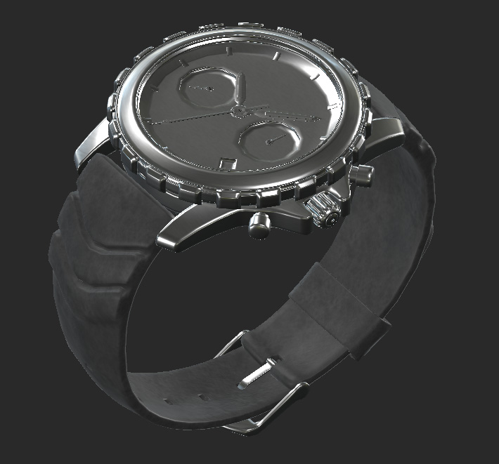
The start of the texturing process of a watch asset with 2 Material nodes and a single mask.
The Material node allows you to texture with a material based workflow. Instead of texturing your individual texture channels one at a time, you define an entire material all at once and then merge multiple together to quickly build up all your texture maps.
Not only does this speed up your workflow, but the ability to share, import and export materials helps productivity among multiple texture artists.
The Material node sits at the heart of Mari's material based workflow and is vital to creating and editing your own materials for texturing. It may be a new style of working inside of Mari so check out the examples to see how it works.
For some quick video tutorials of the new 4.5 Material System, check out Mari 4.5 Fundamentals video series here.
Material Node Inputs
The Material Node by default has no inputs, however when inside of the node you can use an Input node to allow textures and data from your Node Graph to be shared inside the Material node.
Material Node Properties
|
Property |
Description |
|
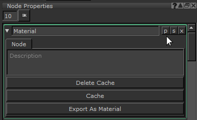
p button |
Clicking the p button allows you to promote attributes and properties from the nodes you use inside the Material node. |
|
s button |
Clicking the s button opens the Material node sub-graph in the Node Graph. |
|
x button |
Clicking the x button closes the Material node properties. |
Export Tab
| Property | Description |
|
Export Path text field, button |
Specify a path to export your material .mma file to using this field. Note: You must specify an Export Path in order to export your material. |
|
Thumbnail Path text field, button |
Specify an image path to be used as the thumbnail image for this material .mma file. |
|
Export As Material button |
Exports the material as an .mma file to the file path specified in Export Path, using the thumbnail image specified in Thumbnail Path. |
Material Node Workflow Example
Creating a Material in Mari
Lets create a quick wooden material that defines every channel you need.
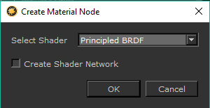
First you need to put down a Material node. A dialog box appears on the UI requiring you to select a shading model. In this example Principled BRDF is selected, but if you want to use another then the principles remain the same.
Note: If you turn on Create Shader Network then a shader is also created that connects the material’s outputs to the shader.
Then to edit it you need to Ctrl + double-click the Material node. This opens up a second tab in the Node Graph containing the Material node contents. To return to your main Node Graph just click the other tab.
Inside this new graph, you can see a number of Output nodes, all named after different texture channels. In here, you can assign textures and inputs to any of the Material node’s outputs.
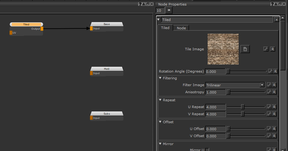
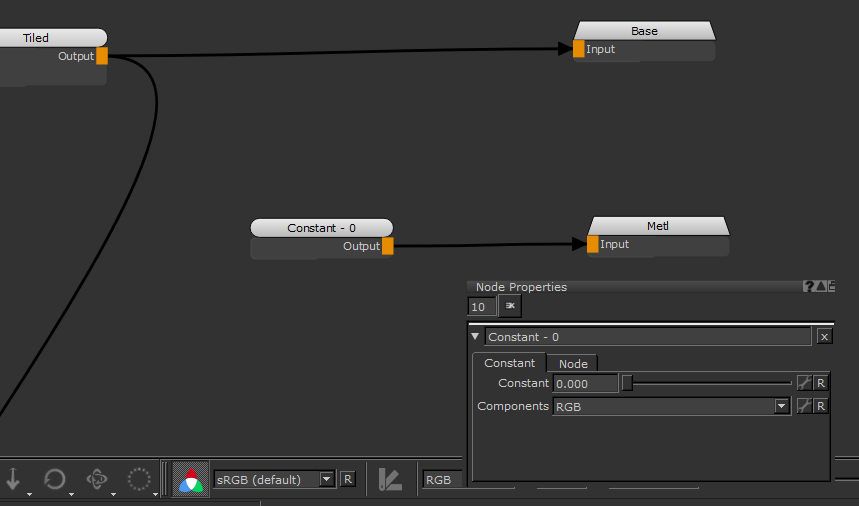
Next we need a tiled texture. You can create one by dragging an image from the Image Manager into the Node Graph. This creates a Tiled node containing your selected image. From there you can change your scale so it looks right for you and make any other edits to the Tiled node until you get something you are happy with. Then it’s time to plug that into the Base Color output.
Next use an HSV node and an Invert node to de-saturate and flip the Tiled node to create a rough map that we can use for the Specular Roughness. You can use a Levels node to adjust the values until you have something that looks right. The easiest way to tell is by going back to your Node Graph and hooking the material up to a shader and viewing it so you can Lookdev values on the fly.
Tip: If you’re unfamiliar with creating and customizing shaders, check out the example documentation for the BRDF and Principled BRDF nodes.
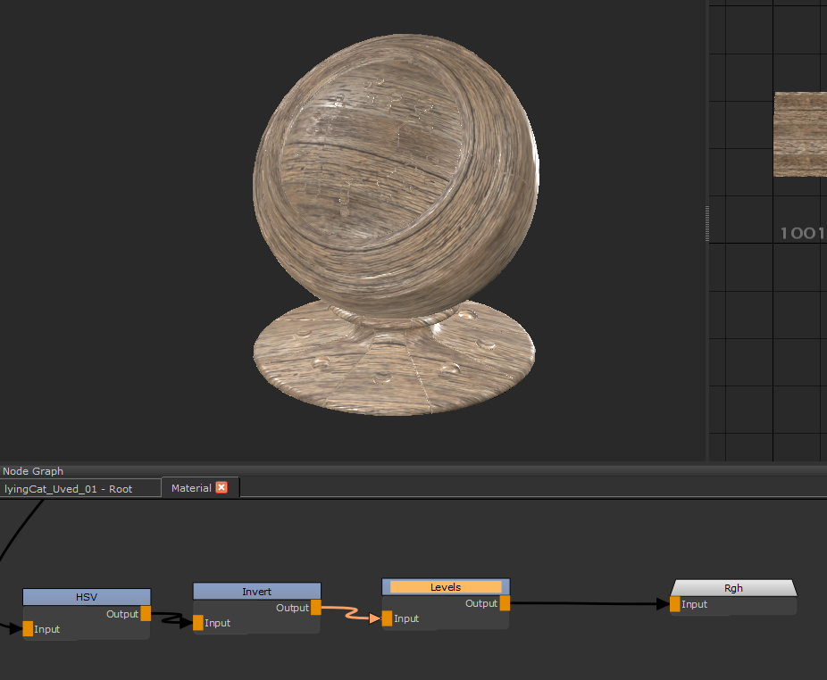
The Base Color and Roughness (Rgh) being viewed through a shader. Going back into the Material node and tweaking the Levels means you can Lookdev as you go.
Adding a Constant node with a Constant value of 0 with RGB components selected can be used for the Metallic output of the material, as the wood for our example is not metallic in appearance.
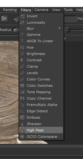
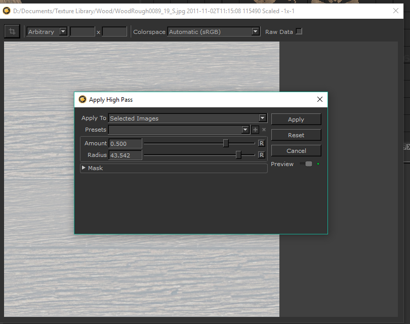
To make a bump map you can use a Filters > High Pass on the wood texture in your Image Manager to get a quick height map from it.
Make sure the Amount stays at 0.5 to get an image with mid-gray as the mid-point as this is what a bump map needs.
You can then use that with another Tiled node that plugs into the Bump output of the Material node. Copying and pasting the first Tiled node used is a good idea so the tiling amount lines up with the base color. In the example is the final result, a quickly built up material you can export and reuse in other scenes.
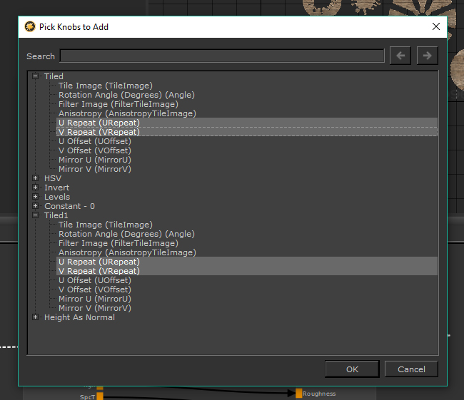
Finally lets promote the Tiled node properties so they can be edited on the fly without having to jump in and out of the node every time. If you jump back to your Node Graph and click the p button on the Node Properties a Group Node Knobs dialog box appears.
From here you need to choose which properties to promote.
Promoting Node Properties
| 1. | Click the Pick option and open up the two Tiled nodes with the plus icon next to their names. |
| 2. | Click to select the U Repeat and V Repeat of both Tiled nodes and click OK. |
They are promoted to the Material node. Now they can be edited on the go without going in and out of the Material node.
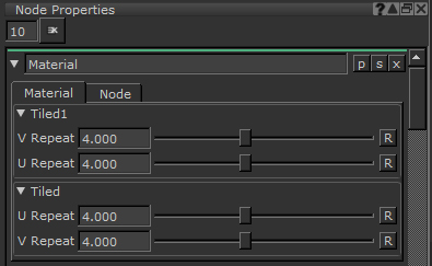
The promoted U Repeat, and V Repeat properties on the Material node.
If you select those promoted properties in the Pick Knobs to Add again, and click the Link button in the same dialog you can merge them all into a single slider of your choosing. Name it something obvious, like ‘TileAmount', and you can now see the new linked attribute in the Node Properties.
That is a way to quickly build up some of the output channels of a Material node from a single tiled texture. You can use this as a base and tweak things or add additional details with other procedural nodes like noises to add detail and complexity.
When you have multiple materials in a scene you can use the Multi-Channel Merge node to combine them together in a similar way to the Merge node.
Related Nodes
Sorry you didn't find this helpful
Why wasn't this helpful? (check all that apply)
Thanks for your feedback.
If you can't find what you're looking for or you have a workflow question, please try Foundry Support.
If you have any thoughts on how we can improve our learning content, please email the Documentation team using the button below.
Thanks for taking time to give us feedback.