3D (OpenGL) Viewport
The 3D viewport is the most frequently used interface in Modo. It is the window into Modo's virtual 3D world. It serves many purposes, allowing you to sculpt, paint, animate, deform, move elements about, and position cameras and lights. With so many jobs to do, it's important that it be flexible as well. There are numerous functions within the 3D viewport that allow you to customize what is seen and how it is seen, depending on the task at hand.
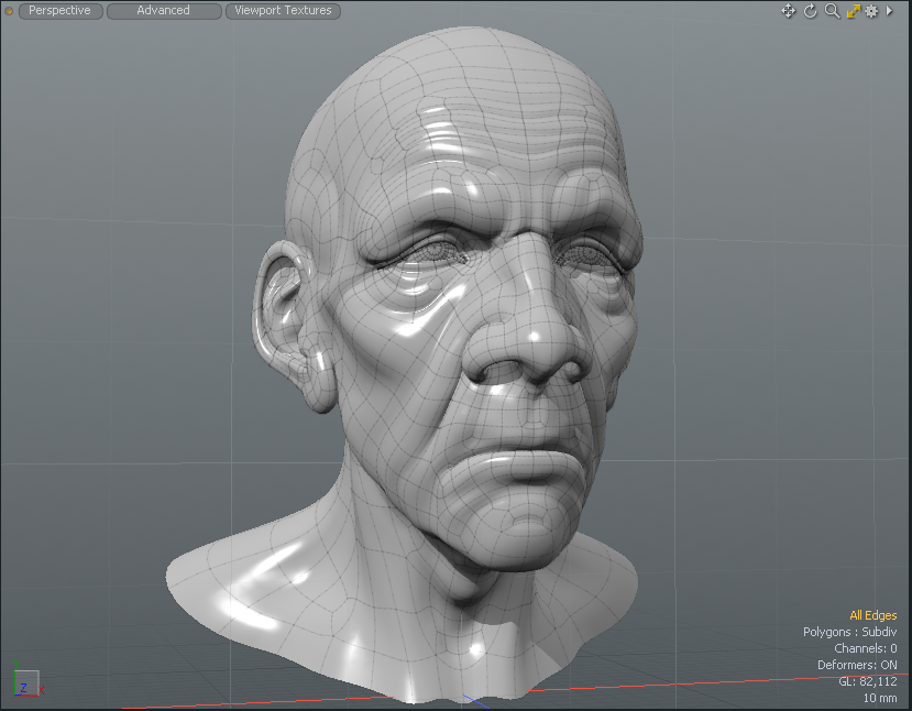
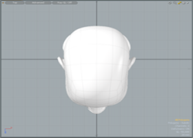
When Modo is opened for the first time, it opens to the default Model layout with a large 3D viewport set to Perspective view. When examining the viewport, you see a dark grid moving in perspective off into the distance some, with another coarser light colored grid perpendicular to the dark one.
Grid Displays
The dark grid represents the ground plane, the zero position of the Y (or Up) axis. Each square of that grid represents a fixed distance. Since this grid is dynamic depending on the zoom level, a small display in the lower right corner gives you the real world equivalent measurements for each square unit, in the case above it is 50mm.
The lighter grid represents Using the Work Plane, which is also dynamic depending on your rotational orientation to the world. While the ground plane is purely for reference purposes, the Work Plane's purpose is to show you where objects get created in the 3D space. Think of it as a construction plane, dynamically adjusting to the most appropriate angle.
Tip: Right mouse click over any Item in the 3D Viewport and select Set Work Plane from the contextual menu to align the work plane to the item center.
Also within the 3D viewport, there are text and information overlays that give you pertinent information with regards to items visible within the viewport as well as guides to selections and the currently selected tool. All of these work together, providing important feedback to speed and enhance the overall workflow.
Additional Controls
To get the most of the 3D views, there are also many additional controls you can directly access when necessary. In the upper left corner of the window is a small circle, called the Thumb. Next to it, there are three capsule shaped buttons. The Thumb is dark gray until a viewport becomes active in which case it turns orange. To make any viewport active, simply click anywhere within the window frame. Right-clicking on the Thumb presents you with a series of options regarding the frame. See Using Layout Controls for further details regarding the options.

The left-most capsule button next to the Thumb is for choosing the way the viewport sees the scene (see Tool HUD). Click on it to open a pop-up menu that allows you to choose fr om the available options of Perspective and various isometric views, or viewing the scene from the Camera or Lights point of view or Ray GL options giving you a fast, fully rendered in-viewport representation of the scene. The Viewport Textures icon allows you to quickly select Environments, Matcaps, and UV Textures to display in the 3D Viewport without having to add them to the Shader Tree. For more information, see Viewport Textures.
The upper right corner has several small icons. The first three let you manipulate the view itself, move, rotate and adjust the zoom level of the active viewport. Clicking and dragging over any of the icons makes the appropriate view adjustment providing an intuitive way for manipulating the position of the viewport's virtual camera. For easier and faster viewport navigation, see Navigation. The next one is the Minimize/Maximize arrow. Click to expand the active viewport to fill the entire local frame, allowing for additional viewport space to manipulate the contents. When the arrow is yellow, click it to minimize the viewport and reveal the other associated viewports.
The gear contains all the available viewport customization control options. Here you can change how the geometry is represented in the viewport, control wireframe overlays and change how items in the background are displayed (items that are visible, but unselected are considered background elements), as well as set the visibility of many individual viewport elements. These options can also be accessed by hovering the mouse pointer over the target window and pressing O on the keyboard. For more information on viewport customization, see below.
The tiny arrow icon to the right, is called the Widget. For more information on this control, see Using Layout Controls. Right-click to open a pop-up menu that allows you to select one of the Modo viewports. Selecting any of these items converts that window into the chosen viewport.
Note: Don't select anything unless you mean to change it, as viewport changes cannot be undone. See Customizing Your Layout for more information regarding viewport customization (and how to get back the default interface when you need to).
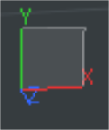
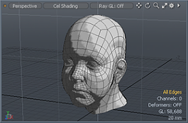
On the lower left of the viewport, there is an XYZ axis gizmo that provides a visual reference to the orientation of the window as well as the current work plane orientation. For orthographic views, the icon displays the axis plane the viewport windows faces toward. In perspective view, you can rotate the view and see the widget update in real time. The lower right corner has several informational text displays that dynamically update, showing the current number of selected items, channels and deformers. The GL display references the number of live polygons active in your viewport (including Sub-D surfaces) and the number at the bottom gives the real world size reference to the squares within the grid of the ground plane. The specific information displayed is controlled in the GL section of the Display Preferences.
Navigation
Modo provides a number of functions to aid in the navigation of GL viewport allowing you to navigate in 3D space in various ways. Most are mouse button and keyboard combinations. Shortcuts are based on the default interface values. For additional navigation options, see Remapping in Input Preferences.
|
Keystroke(s) |
Action |
|---|---|
|
Alt+left-click |
Rotates view
|
|
Alt+middle-click |
Rotates viewport Z axis (bank) view |
|
Alt+right-click |
Flick Rotate (also called Free Wheeling) view slows down when mouse is released. |
|
Shift+Alt+left-click |
Pans View
|
|
Shift+Alt+right-click |
Up/Down Pan only |
|
Ctrl+Alt+left-click |
Zooms to mouse position |
|
Ctrl+Alt+right-click |
Box Zoom (drag box to zoom) |
|
. (period) |
Zooms In |
|
, (comma) |
Zooms Out |
|
G |
Centers view (Current mouse position to viewport center)
|
|
/ |
Turns (Spinning view of scene) |
|
Shift+/ |
Turns upright |
|
Mouse Wheel Scroll |
Zooms view in & out to mouse pointer |
|
A |
Fits (Zoom to scene extents/all Items) |
|
Shift+A |
Fits selected (Zooms to selected elements) |
|
Ctrl+A |
Aligns selected (Aligns view to current selection) |
|
Ctrl+Shift+A |
Fits and aligns selected (Zooms and aligns view to current selection) |
|
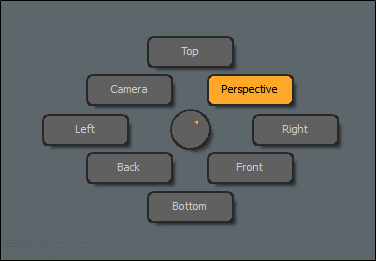
Ctrl+ Spacebar |
Displays a pie menu. Hover your cursor over any of the options and release to select a view.
|
Visibility
Modo provides a way to modify the visibility of object in the viewport directly. While generally you can toggle visibility of items in the Items List that changes visibility of the entire layer. The following commands allow the temporary toggling of visibility of only the selected element, including components, depending on the selection mode. Once hidden, geometry becomes uneditable. To hide a piece of geometry, select the geometry component you wish to hide and in the menu bar, go to View > Hide Selected or press H on the keyboard. To make the geometry visible again, click View > Unhide or press the U key.
Note: When a file is saved and re-opened later, all hidden polygons are visible.
|
Keystroke(s) |
Action |
|---|---|
|
H |
Hides selected geometry (hides all if nothing is selected). |
|
Shift+H |
Hides unselected geometry. |
|
Ctrl+H |
Hides invert (toggles visibility, inverting the present state). |
|
U |
Makes all hidden geometry visible for the currently selected layers. |
Locking
Providing a similar function to hiding, locking allows you to fix a selection of geometry so that it is not editable, however it is still visible.
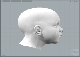
Courtesy William Vaughan
To lock item layers:
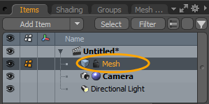
| 1. | On the right panel, open the Items List, and right-click the item you want to lock. |
| 2. | Select Lock/Unlock from the dropdown menu. |
A lock icon appears on the mesh item in the Items list.
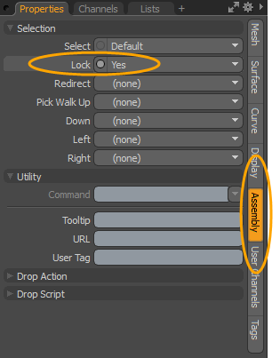
• Alternatively, in the Properties tab of the selected mesh item, open the Assembly tab, and set Lock to Yes. For more information, see Assembly Viewport.
You can unlock a locked element by right-clicking on the item and selecting Lock/Unlock. The lock icon is removed when unlocked.
While working in the 3D viewport, you can lock selected components to assist you in your workflow. Modo displays locked polygons, vertices, and edges with a specific color in the 3D viewport.
Note: In edge selection mode, Modo also displays locked vertices since the locked edge elements are associated with vertex or polygon elements.
To lock a component selection of geometry in the 3D viewport:
| 3. | In the 3D viewport, select the geometry you wish to lock using one of the selection modes (Vertices, Edges, Polygons, or Items). |
For more information about selecting geometry, see Selecting Items.
| 4. | In the menu bar, click Edit > Lock Selected or press J. |
Tip: You can unlock any locked elements in the 3D viewport by clicking Edit > Unlock or by pressing I.
|
Lock Key Shortcuts |
Action |
|---|---|
|
J |
Locks selected geometry (locks all if nothing is selected). |
|
Shift+J |
Locks unselected geometry. |
|
Ctrl+J |
Locks invert (toggles locked state of all geometry). |
|
I |
Makes all locked geometry editable. |
To change the color of locked elements:
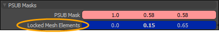
| 1. | In the menu bar, click System > Preferences, expand Display, and click Colors. |
| 2. | Under PSUB Masks, set the Locked Mesh Elements color by clicking-and-dragging the values in the field or click on the field to open the Color Picker to select your color. For more information, see Color Picker Viewport. |
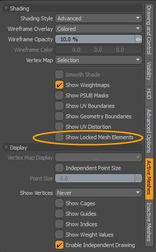
To disable Show Locked Mesh Items:
By default, Modo displays locked mesh items in the viewport. You can disable this in the viewport properties.
| 1. | In the top-right corner of the 3D viewport, click the gear icon to display the properties. |
![]()
| 2. | Open the Active Meshes tab, expand the Shading section, and uncheck Show Locked Mesh Items. |
Tool HUD
The Tool HUD is available in every layout of the 3D viewport. It is a context-sensitive form containing the most recent tools for each layout. It also displays different sets of tools depending on the active selection mode.
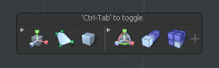
To enable the Tool HUD press Ctrl/Cmd+Tab on the keyboard.
When you first open the Tool HUD , it displays a set of custom tools for the particular layout and selection mode. As you keep using various tools, they are added to the Tool HUD's most recent tools section on the left.
When you click a tool in the Tool HUD, the tool becomes active and its icon is highlighted in orange until you drop it.
You can add new tools to the Tool HUD by activating the tool, then clicking the + button on the right.
To remove a tool, click x in the upper-right corner of the tool's icon in the Tool HUD.

You can customize the Tool HUD in the 3D Viewport Properties, in the HUD sub-tab. For more information, see 3D Viewport Properties.
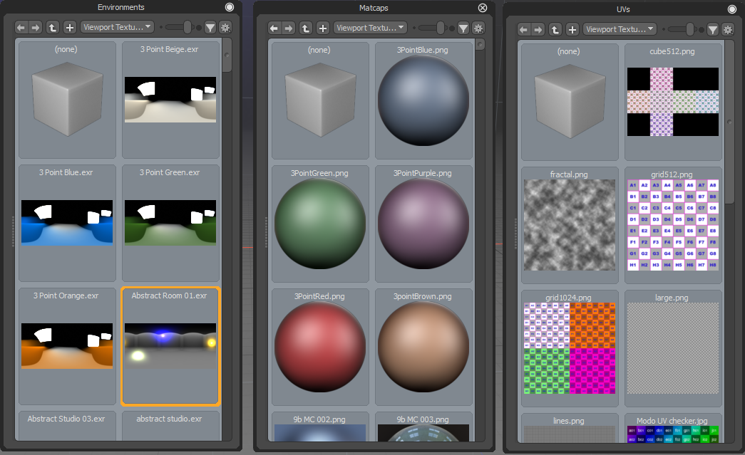
Viewport Textures
Predefined textures can be applied to your scene to quickly see a preview in the 3D Viewport using any of the 3D Viewport Styles. A variety of environments, MatCaps shaders, and UV textures are available. When you double-click on a texture, your scene is updated in the 3D Viewport without having to add any items in the Shader Tree. Using this feature enables you to experiment with different textures before actually creating Shader Tree layers. For more information, see Shader Tree Item Layers.
Note: Items that you have set in the Shader Tree are not overwritten. To view your set Shader Tree items, click Render > Open Preview and click the arrow to render your scene.
The following options are available:
|
Option |
Description |
|
Environments |
When an environment texture is set, Modo replaces the Environment item in the Shader Tree. |
|
Matcaps |
When a MatCap shader is set, Modo completely replaces the surface shader used in the Shader Tree with the selected MatCap shader. |
|
UV Textures |
When a UV texture is set, Modo replaces the Diffuse texture applied on the mesh surface and uses a default material. A number of provided UV Textures are used for UV Diagnostics. Note: When applying UV Textures to a Preset mesh, the UV Map name for the UV Texture must be the same as the UV Map name used by the Preset. |
View Types
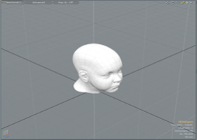
While viewports have no actual camera, Modo does provide you the ability to change how a scene is viewed through the viewports. The options can be selected from the View Type menu in the upper left corner of the viewport. Click on the button to open the menu where you can choose alternate options. The following orthogonal views provide viewpoints free from perspective distortion of all the cardinal viewing planes -front, back, top, bottom, left and right.
|
|
|
|
|
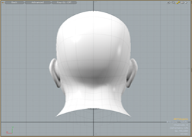
Front |
Back |
Top |
|
|
|
|
|
Bottom |
Left |
Right |
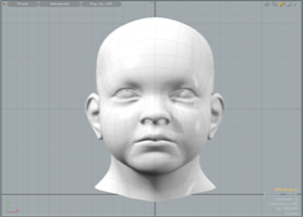
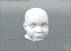
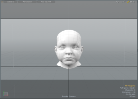
Perspective views are similar to viewing the scene through a real-world camera, where the displays have perspective and a vanishing point. The amount of perspective distortion can be controlled in the menu bar, on Windows, in System > Preferences > Display > OpenGL setting Flatness of Perspective and on Mac OS, Menu > Preferences > Display > OpenGL setting Flatness of Perspectivein (This is for the Perspective view only, the Camera and Light views are controlled by the item's settings). Additionally, you can view a scene from the Camera's point-of-view, mimicking the field of view settings of the item. When in the Camera mode, translucent black bars appear over the frame to represent the rendered frames aspect ratio, for when it doesn't match that of the viewport frame. Finally, there is also the Light view that displays the scene from a particular light's point-of-view, providing an easy way to see what the light is pointed at and illuminating.
Note: When navigating in the Camera or Light views, you are actually moving the positions of the elements within the scene.
|
|
|
|
|
Perspective |
Camera |
Light |
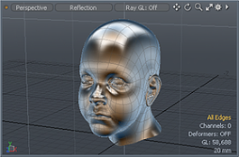
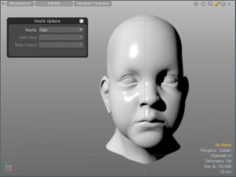
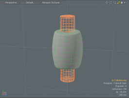
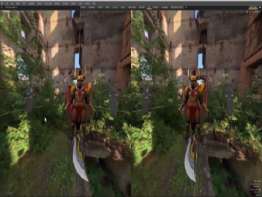
Ray GL
The Ray GL viewport option leverages Modo's render preview functionality overlaid with the standard viewport options to provide a hybrid display of the rendered scenes, where you can model and interact with the rendered scene directly. To use it, click the center button on the top left of the 3D viewport and select Ray GL.
There are three options to choose from:
• Full - Nearly approaches the quality level of a final render but with a reduced ray amount for faster interaction.
• Fast - Forgoes textures for a speedier preview of the scene.
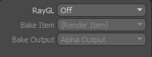
• Bake - Provides a preview of a bake. When selected, choose from the following options:
• Bake Item - Select the bake item to use for the bake:
- (Render Item) - Bake via the Render Items.
- (Current Bake Item)- The currently selected bake item.
- One of the other bake items in the scene.
• Bake Output - Choose from one of the available outputs for the currently selected bake item. Outputs can be render outputs or texture outputs from a bake item. Texture outputs are based on the selected texture effect.
For more information see Working with Bake Items and Baking Tools
For simpler scenes, shading is near real-time, just like in the render preview, but for more complex scenes, there is a lag between edits, where the system temporarily reverts back to the standard GL view. Users can control how Ray GL updates based on options available within the RayGL Preferences available on Windows in System > Preferences > Display > Ray GL and , on Mac OS in Menu > Preferences > Display > Ray GL. Additionally, you can choose which elements are taken into account when rendering. For example this can be useful when you want to disable fur rendering to speed up the preview when modeling an object with complex fur.
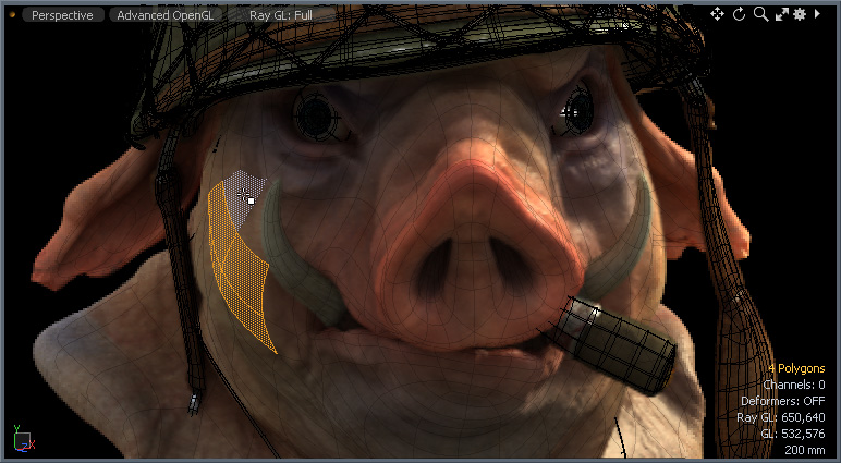
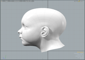
Model courtesy of John Hayes
3D Viewport Styles
Modo provides a number of ways to visualize a scene using viewport styles. These are in-viewport shaders that display the geometry in specific ways, making it easier to visualize certain aspects of a model or scene. You can choose from the available options by using the Viewport Options button within the viewport (the second button from the left on the top).
|
Layout |
Description |
|---|---|
|
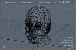
|
In the Wireframe drawing style only vertices and the edges that connect them to make polygons are visible. The actual polygon faces are not drawn, and as such, you can see through the model to vertices and polygon edges on the backside as well. |
|
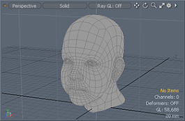
|
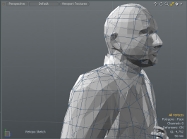
The Solid shading mode renders the geometry without shading. This mode is most useful when combined with a wireframe overlay, resulting in a flat rendered sketch mode. |
|
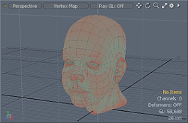
|
The Vertex Map shade option uses the currently selected Vertex Map to shade the model. In the case of Vertex Color maps, the color of each vertex is blended with the colors of the neighbor vertices. For Weight Maps, positive values shade red while negative values shade blue. Any vertex with a value of 0 or no value at all is shaded green. If Color and Weight type Vertex Maps are selected, the Color Vertex Map takes precedence. |
|
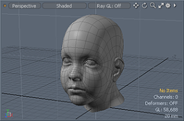
|
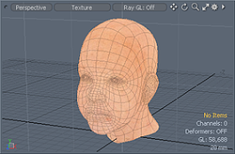
The Shaded style shows meshes with their basic material definitions such as Diffuse, Specular and Transparency. No image maps appear in the Shaded style. |
|
|
The Texture style shows the mesh surface with only the most basic material attributes including any image map textures. In Texture style, RGBA images can be seen with their alpha blending them into the material beneath. However, limitations of standard Open GL force the image map to draw without shading (that is, full bright). This is a reasonable view style for 3D painting or placing image decals onto a model. The Shaded Texture style can shade the image texture but cannot use alpha channel. The Advanced view correctly alpha blends multiple image texture layers and shades them appropriately. |
|
|
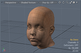
In the Shaded Texture view, image maps are visible as blended with the light shading effects. Due to OpenGL limitations this mode cannot show images with alpha channels, so any RGBA image appears as an opaque RGB image. To see alpha channels from the image, use the Texture, Default or Advanced view styles. |
|
|
The Default view allows you to see many more effects than the normal Texture view. With Default mode you can see the following types of image maps: Color, Bump, Specular, Luminous and Transparency. It blends multiple layers of each (though Bump only uses the first layer). However, the total number you actually see at a time is based on the resources of your graphics card. These resource limitations are per Shader Tree surface so if your card has 8 texture units, each Material can have up to 8 image maps. Aside from simple alpha blending, each layer's opacity is respected as well as the base material settings - so you can, for instance, set the material to be 50% transparent, then create a clip and apply it as a transparency map and paint in areas of complete transparency or complete opacity (previously referred to as Advanced GL). |
|
|
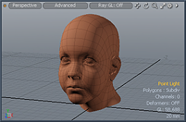
The Advanced viewport provides a more powerful rendering mechanism by using modern graphics technology. The purpose of this viewport is to be able to produce closer results to the final offline render of scenes, within an interactive manner. Supporting more functionality than the 'Default' view, the Advanced viewport supports reflections and fresnel of the Physical Shader, fur materials, as well as 'Ambient Occlusion' and Direct Light shadows and has its own viewport antialiasing. These functions, and more, can be enabled and controlled in the Viewport options panel (see 3D Viewport Properties: Advanced Options ). A graphics card with at least OpenGL 3.2 support is required for Advanced Viewport, and the VBO mode must be enabled. When activated, toggle buttons are displayed in the 3D viewport allowing you to select a shading mode. Select one for the following: Note: Group Masks are supported in the Advanced 3D viewport, allowing you to work on complicated material setups directly in the viewport and to make changes in real time. There is little difference between the representation of a material in the Advanced 3D viewport and the representation of a material in Modo’s Preview Viewport. |
|
|
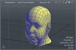
The Gooch shading mode is a vertex shading algorithm that displays the geometry using a technique known as tone shading. Rather than relying on the traditional light to dark shadow style shading, which can obscure parts of the model while working, tone mapping represents the curvature of the geometry, shading warm-to-cool where the warm areas are those that would traditionally be lit and the cool areas are those that would normally be in shadow. This shading mode allows you to check the surface of your model for proper contouring while still seeing the entire mesh evenly lit. |
|
|
The Cel Shading style creates a stepped shading on the model to appear as if it were a cartoon with a fixed number of shading zones. |
|
The Reflection shader displays your geometry as if it were fully reflective. This shader uses a cubic reflection map, and mixes in some of the original material properties with a small amount of shading to properly show object contours. This mode is very useful when performing visual review of a models surface as it assists in finding surface irregularities. |
|
The RayGL shader leverages Modo's render preview functionality overlaid with the standard viewport options to provide a hybrid display of the rendered scenes, where you can model and interact with the rendered scene directly. |
|
|
The Fusion Profile shader leverages Modo's MeshFusion functionality. |
|
|
The HMD quality presets provide a high quality image display. Select one of the presets, High, Low, Mid, or Ultra, for better performance in the HMD. Tip: If you are experiencing visual performance issues, select a lower HMD quality preset. For more information, see Options, Scenes, and Performance. |
|
The Model Base returns back to the default Model layout after selecting a previous viewport style. |
|
The MeshFusion Shader leverages Modo's MeshFusion functionality to display meshes drawn in wireframe: the primary mesh is green, and the trim is magenta. They are color-coded in the Item List as well. |
|
The Topology Shader displays the Topology preset in the 3D viewport. You can activate this when using the Model layout. |
|
Save Viewport Preset allows you to save the 3D view as a preset and to specify if Drawing, Visibility, Active Meshes, Inactive Meshes and Advanced viewport options are included. Once done, this viewport is listed in the 3D Viewport Styles dropdown menu. |
|
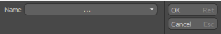
Delete Preset allows you to select a viewport preset to delete. |
Viewport Toggle Buttons
![]()
Use any of the following toggle buttons to quickly enable common options while working on your scene.
|
|
Viewport Textures |
Applies a predefined texture to your scene to quickly see a preview in the 3D Viewport using any of the 3D Viewport Styles. A variety of environments, MatCaps shaders, and UV textures are available. For more information, see Viewport Textures. |
|
|
Replicators |
Sets how the replicators are displayed in the 3D viewport. The following options are available: • None - Draws all replicators as a bounding box. Choose this option for best performance. • Selected - Displays shaded replicators for only those selected. • All - Shades all replicators in the 3D viewport. |
|
|
Show Weightmaps |
Displays the selected weigh map on the geometry in the 3D viewport. |
|
|
Show UV Distortion |
Displays the UV distortion on the geometry in the 3D viewport. Note: A UV map must be selected to be visible in the 3D viewport. |
|
|
Reference Item |
Aligns the coordinate system to the selected item. |
|
|
Show Locators |
Toggles the visibility of the locator items in the 3D viewport. |
|
|
Overlay Drawing |
Toggles the visibility of locator items through objects. |
|
|
Make Inactive Invisible |
Hides inactive layers in the 3D viewport. |
|
|
Make Inactive the same as Active |
Draws the inactive layers in the same styles as the active layers. |
|
|
When the Advanced viewport style is enabled, displays the basic geometry shading and materials. Use this shading mode for basic modeling. |
|
|
|
When the Advanced viewport style is enabled, displays basic shading, materials, shadows, and IBL lighting. Use this shading mode to balance speed performance and quality. |
|
|
|
When the Advanced viewport style is enabled, displays the highest quality shading and materials. Use this mode when working on textures and final render Playblast. Note: The complexity of the Shader Tree setup may affect performance. For example, if you have several layers under the parent shader item, it may take longer to display. |
Advanced Viewport Toggle Buttons
When the Advanced viewport style is enabled, the following toggle buttons are displayed in the 3D viewport.
|
|
Displays the basic geometry shading and materials. Use this shading mode for basic modeling. |
|
|
|
Displays basic shading, materials, shadows, and IBL lighting. Use this shading mode to balance speed performance and quality. |
|
|
|
Displays the highest quality shading and materials. Use this mode when working on textures and final render Playblast. Note: The complexity of the Shader Tree setup may affect performance. For example, if you have several layers under the parent shader item, it may take longer to display. |
Viewport Light
You can adjust the default lighting in a 3D viewport using the options found under View > Edit Viewport Lights. Once the function is active, you can click and drag in the viewport to change the current light's position. Additional properties are available in the Tool Properties for Color and Intensity. Current defines the particular light being edited. There are two lights by default. You can use the commands View > Add Viewport Light and View > Remove Viewport Light to modify the number of lights visible.
Viewport Presets
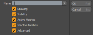
Under the viewport Styles menu there is an option to save a viewport Preset allowing you to capture all the current viewport settings and easily recall them at a later time. When the command is invoked, the following panel opens up.
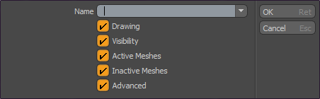
In the Name input field you specify a title for the Preset. This is the name that appears in the menu once saved for later recall. The option toggles represent the various options as defined in the associated viewport Options panel (covered below), allowing you to control specifically which setting is recalled with the saved preset. Directly under the Save Preset option is an additional command allowing you to delete any user-created viewport preset.
Contextual Menus
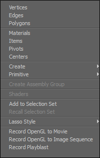
By right-clicking in the 3D Viewport in an empty scene, you are shown a contextual menu to assist you in your design workflow. As you select items that you have added to your scene, you can right-click on an item to view a contextual menu to display another set of related tools for your use. The following is an example of the contextual menu presented in an empty scene.
|
Option |
Description |
|
Vertices |
Change the selection mode to Vertices. |
|
Edges |
Change the selection mode to Edges. |
|
Polygons |
Change the selection mode to Polygons. |
|
Materials |
Change the selection mode to Material selection. |
|
Items |
Change the selection mode to Items. |
|
Pivots |
Change the selection mode to Pivots. |
|
Centers |
Change the selection mode to Centers. |
|
Create |
Create a Modeling with Images, Camera Items, Locator Item, Mesh Item, and a number of other Modeling Operations. |
|
Primitive |
Add a number of Adding Primitives to your scene. |
|
Create Assembly Group |
Create an Assembly Group. For more information, see Assembly Inputs and Outputs |
|
Shaders |
Assign an image-specific Shader. |
|
Add to Selection Set |
Add the selected elements to a Selection Set. For more information, see Using Selection Sets. |
|
Recall Selection Set |
Recall any existing selection set. For more information, see Using Selection Sets. |
|
Lasso Style |
Change the Lasso style to Lasso, Rectangle, Circle or Ellipse. For more information, see Lasso. |
|
Record OpenGL to Movie |
Save your scene as a movie file. A number of file formats are available. |
|
Record OpenGL to Image Sequence |
Save your Image Sequence. A number of file formats are available. |
|
Record Playblast |
Set Playblast settings. For more information, see Playblast. |
3D Viewport Properties
Allows you to further customize the display of elements within a viewport. The default interfaces apply varieties of these options to their custom workspaces, however, they have been fine-tuned to the degree that they rarely need adjusting.
If required, you can easily access the display menu options by clicking on the gear icon in the upper right corner of the viewport, or moving the pointer over the target viewport and pressing O to open the pop-up menu.
You can dismiss the window by clicking anywhere in the interface.
Note: Edits are made per-viewport.
The following options are available for modification.
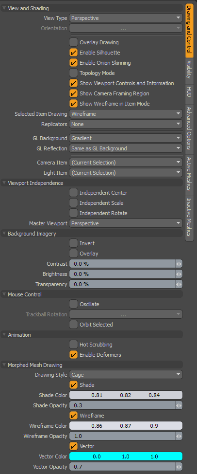
3D Viewport Properties: Drawing and Control
View and Shading
Note: The Enable Silhouette, Topology Mode and Show Weightmaps options are all incompatible with each other and therefore cannot all be enabled at the same time. The Show Weightmaps option supersedes the Enable Silhouette option and the Topology Mode options supersedes both.
• View Type - Choose from the various view types covered in the 3D (OpenGL) Viewport section: Top, Bottom, Back, Front, Left, Right, Perspective, Camera and Light.
• Orientation - For the orthogonal views only, you can control upright rotation angle in 90° increments.
• Overlay Drawing - For custom draw items, such as locators, cameras and lights (that have no inherent geometry) this option enables an X-Ray style of viewing, meaning you can see these elements through polygons when enabled.
• Enable Silhouette - When this option is enabled (the default state), any Mesh Item designated in its display properties as Show as Silhouette displays as a flat solid shape with no interior details. This option should be thought of as a global enabler only, where the actual display of the silhouette itself is determined by the options of the item's Display properties.
• Enable Onion Skinning - When this option is enabled, any Actor with Onion Skinning defined for it displays as designated in the 3D viewport (the default state).
• Topology Mode - This option aids the process of retopologizing a mesh, sometimes also called simply topo. This is the process of converting a high resolution mesh to a low resolution mesh by creating new polygons against the high resolution mesh set as a background element. Generally, this process creates intersecting geometry that is difficult to see. Enabling the Topology Mode: This option forces the drawing of vertices and edges to always draw in front of background elements in the scene. Polygons are displayed as semi-transparent shapes with solid blue edges. Vertices are enlarged for easier visibility.
• Show Viewport Controls and Information - This toggle controls the display of all the viewport element overlays, such as the axis widget, move, scale and Rotate tool's and the information overlays. When the controls are disabled, you can press O while hovering the mouse pointer over the target viewport to open the viewport options panel again.
• Show Camera Framing Region - This option allows you to toggle the visibility of the camera framing regions in the 3D Viewport. Click the image below to view an animation.
• Show Wireframe in Item Mode - Toggle to enable wireframe drawing in Item mode, giving a cleaner display to differentiate between Item and Component modes.
Note: Setting this option overrides the settings in the Active Mesh and Inactive Mesh tabs. For more information, see 3D Viewport Properties: Active Meshes and 3D Viewport Properties: Inactive Meshes.
• Selected Item Drawing - Selected items are drawn as a wireframe (the default) with a transparent fill color over the mesh.
The following options are available:
- The selected items in the scene are displayed as a wireframe with a transparent fill color over the mesh.
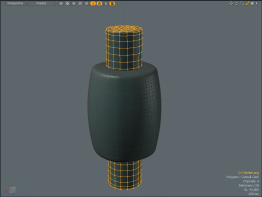
• Filled - The selected items in the scene are displayed with a transparent yellow mesh. Roll over an item in your scene to display the item in a transparent light blue mesh.
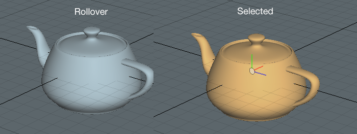
• None - The selected item in the scene is displayed in a fill color and the unselected items in the scene are drawn in wireframes.
• Replicators - This option allows you to control the shaded display of any Replicator in a scene. You can adjust this setting to never (None), or always (All) display shaded Replicators, or only when a Replicator Item is active (Selected). Otherwise, the Replicator clones are displayed as bounding boxes. For more information, see Replicators.
• GL Background - You can choose from several viewport-specific GL background options for controlling what is seen in the background of the viewport.
• None - Displays no background, only the defined viewport color is visible.
• Gradient - Displays a gray gradient shading that is multiplied over the viewport color.
• Environment - Displays the settings as determined by the Environment Item of the Shader Tree, simulating the rendered output.
• Image - You can define a custom image for use as a viewport background. When this option is selected, a file requester opens where you can select or navigate to the appropriate image. For best results, image should be a spherical projection.
• GL Reflection - You can choose from several viewport-specific GL reflection options for controlling the display of reflective surfaces.
• None - Displays no reflection, ignoring surface material settings.
• Gradient - Displays a gray gradient shading on reflective surfaces.
• Environment - Displays the settings as determined by the Environment item of the Shader Tree, simulating the rendered output.
• Image - You can define a custom image for use as reflections (only applies to custom reflective surfaces, or Reflection viewport display mode. When this option is selected, a file requester opens, where you can select or navigate to the appropriate image. For best results, the image should be a spherical projection.
• Same as GL Environment - Reflection options are determined by the GL Background settings.
• Camera Item - In the case of multiple cameras in a scene, where the viewport is set to Camera view type, this option determines which camera item controls the viewport. Selecting alternate cameras changes the viewport to that camera's point of view.
Note: Navigating in the viewport while in this mode physically moves the camera in the scene.
• Light Item - In the case of multiple lights in a scene, where the viewport is set to Light view type, this option determines which light item controls the viewport. Selecting an alternate light changes the viewport to that light's point of view.
Viewport Independence
• Independent Center/Scale/Rotate - To make viewport navigation easy, it is sometimes desirable to link or unlink grouped 3D viewports, so when changing the position, size and angle of the viewport view, associated viewports move in sync with the active viewport. These three toggles allow you to control the syncing of the view properties center, scale and rotate.
• Master Viewport - Determines the linking of viewports, on a per viewport basis, using the Orthographic, which links all associated orthographic viewports, and Perspective, which links associated perspective views (does not include camera and light views).
Background Imagery
For scenes using Front type texture projection method in the environment item, either from a camera or light, the background imagery options control the display of the projected environment image in the viewport. To use it, apply an image to the Environment item in the Shader Tree, and in its associated Texture Locator, assign the Front projection type, and specify a camera or light if necessary. For more information on Texture Locators, see Texture Locator .
• Invert - Inverts the RGB values of the projected image.
• Overlay - When enabled, this option draws the projected image on top of the viewport, obscuring its contents. When set as such, changing the Transparency allows you to see the viewports contents.
• Contrast - This option adjusts the contrast of the projected viewport image, modifying the visual difference between light and dark values in the image. Positive values increase the contrast, while negative values decrease it.
• Brightness - This option adjusts the brightness of the projected viewport image. Positive values brighten or lighten the image, while negative values darken it.
• Transparency - This option changes the opacity of the viewport projected image. When set to Overlay, it affects the visibility of items in the scene through the image. When overlay is disabled, this value reveals the settings of the background options.
Mouse Controls
• Oscillate - In the Perspective view type, you can enable the Oscillate option. Then, using Alt+right-click , drag the cursor, moving the view. When you let go of the mouse button, Modo continues to bounce back and forth, oscillating over the previous mouse movement. This is useful when you want to view a model in motion.
• Trackball Rotation - You have several options for orbiting behavior when navigating the viewport. Trackball style navigation is a common way to rotate the view of a scene, as if the viewport itself was a giant trackball, allowing multiple axes rotation based on the mouse's viewport position. Disabling this option limits viewport rotations to only two axes. The options are:
• No - Disables trackball style rotation in favor of standard upright orbiting.
• Yes - Enables trackball rotation for the specific viewport.
• Default - Uses the preference setting available on Windows and Linux in System > Preferences > Input > Remapping > Viewport Rotation and on Mac OS in Menu > Preferences > Input > Remapping > Viewport Rotation.
• Orbit Selected - When this option is enabled, Modo automatically orbits around the selected element, using the selection's bounding box center as the center of rotation.
Animation
• Hot Scrubbing - When enabled, animated items in the scene update continuously when dragging the Timeline, producing a smooth motion. When disabled, items only update when the mouse pauses, or isn't moving, providing slightly faster performance.
• Enable Deformers - This toggle allows viewports to display the results of animated morph and Vertex Map deformers in the viewport. By default, this option is enabled in all built-in 3D viewports.
Note: When this option is disabled, mesh operations are not displayed in the viewport.
Morphed Mesh Drawing
• Drawing Style - Specify how you would like to draw Morph Maps. The following options are available:
• Default - Modo draws the traditional morphed mesh.
• Cage - Modo draws the base mesh and the morphed mesh as a cage. When this option is selected, additional properties are revealed:
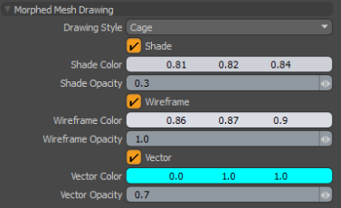
• Shade - Draws a transparent morphed mesh as a cage.
• Shade Color - Specifies the color of the morph cage. Note, only displayed when a Shader, Wireframe, or Vector is enabled.
• Shade Opacity- Specifies the opacity value of the morph cage.
• Wireframe - Draws the cage in wireframe mode.
• Wireframe Color - Specifies the color of the wireframe.
• Vector - Draws line segments from the vertices of the base mesh to the corresponding vertices of the morph mesh.
Note: To display a morphed mesh, you need to select a morph map with Enable Deformers disabled.
• Vector Color - Specifies the color of the vector lines.
• Vector Opacity - Specifies the opacity value of the vector lines.
3D Viewport Properties: Visibility
Item Visibility
• Show Lights - Toggles the visibility of the light item representations in the current viewport. Typically disabled for modeling views.
• Show Cameras - Toggles the visibility of the camera item representations in the current viewport. Typically disabled for modeling views.
• Show Locators - Toggles the visibility of the locator item representations in the current viewport.
• Show Texture Locators - Toggles the visibility of the texture locator item representations in the current viewport.
• Show Meshes - Toggles the visibility of Mesh Items in the current viewport.
• Show Instances - Toggles the visibility of instance items in the current viewport.
• Show Pivots/Centers - Visibility for pivot and center representations can be determined by these criteria:
• None - Only shows the pivot/center when in Pivots/Centers selection mode.
• Selected - Shows the pivot/center when any item layer is selected in the Item List.
• All - Always shows the pivot/center for all items.
General Visibility
• Show Work Plane - Toggles the visibility of the Work Plane in the current viewport. (keyboard shortcut is Num Pad *).
• Always - Set to always display the Work Plane. This is the default option.
• Active - Set to display the Work Plane when it has been active. For example, moved or rotated.
• Never - Set to never display the Work Plane.
• Show Grid - Toggles the visibility of the ground plane grid at the 0 position of the up axis.
• Always - Set to always display the grid.
• Inactive Work Plane - Set the main grid to be drawn when the work plane is not active. This has the effect of there being only one grid drawn at a time. This is the default option.
• Never - Set to never display the grid.
• Draw Faded Grid - Toggles the visibility of the main grid and Work Plane to be drawn faded.
• Faded Grid Color Axes - Toggles the visibility of the main grid and Work Plane to be drawn with colored axes.
• Show Backdrop - Toggles the visibility of any Backdrop Image items in the scene. For more information on Backdrop Images, see Modeling with Images.
Selection Visibility
• Show Selections - Toggles the visibility of selection highlighting.
• Show Selection Normals - When enabled, this option displays normals for any selected polygon(s), displayed as a small dashed line pointing outward from the center of the polygon. Normals represent the facing direction for polygons.
• Show Selected Filling - Toggles the visibility of the selection highlight overlay.
• Show Selected Outline - Toggles the visibility of the selection highlighting outline.
• Show Selection Rollovers - Toggles the visibility of selection rollover pre-highlighting.
Performance
By disabling some of these options, the performance is improved in the 3D viewport when you are working with complex models.
• Fur - Toggles the visibility of fur material applied to your mesh.
• Displacements - Toggles the visibility of Displacement maps.
• Mesh Smoothing - Toggles the settings applied to smooth geometry. When enabled, polygons shade according to the material Smoothing setting.
• User Shader Tree - Toggles the materials and textures created in the Shader Tree.
3D Viewport Properties: HUD
• Show Viewport HUD - Toggles the visibility of the Tool HUD. Press Ctrl + Tab to toggle the HUD off and on.
• HUD Property Form - Specifies what property form the Tool HUD uses. You can customize the property form in the Form Editor, available from the menu bar. Click System > Form Editor. In the editor, the available property forms are listed under Form HUD.
• HUD Style - Specifies how the Tool HUD is displayed. The following options are available:
• fixed - Sets the Tool HUD to a fixed position.
• floating - Allows the Tool HUD to be moved around.
• Close - Transforms the Tool HUD into a moveable palette with a Close button.
• Allow HUD Customization - When enabled, you can add new tools to the Tool HUD and remove existing ones. When disabled, the set of tools in the Tool HUD can't be edited.
3D Viewport Properties: Advanced Options
The Advanced Viewport options control the settings applied only to the Advanced viewport display style.
Effects
• Ambient Intensity - Adds an even illumination globally to all diffuse surfaces in a scene. This is especially useful for simulating additional bounces of light.
• Ambient Color - Allows you to specify a color value for the global light added by the Ambient Intensity setting.
Note: Ambient Intensity and Ambient Color are also available in the Render Items's Global Illumination settings. The Global Illumination settings are applied at render time, and override the viewport settings.
• Show Shadows - Toggles the visibility of Direct Light shadows in the viewport. Note that Point, Directional, and Spot Lights generate more accurate shadows than Area and Cylinder lights.
• Shadows CSM - Increases or decreases the shadow quality displayed in the viewport. You can set the number of shadow buffer projections the Cascade Shadow Map system uses for the light source to view casting curved shadows on curved surfaces. The following options are available: off, x2, x3, and x4. The higher the value specified, the smoother the shadow edges are. By default, this option is set to x2.
Note: The higher the level specified, the more memory and processing time are required. (Lower values render faster but produce less shadow detail.)
• Shadows Resolution - Sets the texture resolution used when depth projecting the shadows. The following options are available: Low, Mid, and High. By default, this option is set to High.
• Shadows Filter - Sets whether the shadows are filtered. By default, this option is On. When working in a complex scene, turn this option off to improve performance in the 3D viewport.
• Use Normal Maps - Toggles all normal map visibility.
• Use Bump Maps - Toggles all bump map visibility.
• Materials - Overrides the Shader Tree materials being used in the scene. This setting provides faster rendering performance results in the Advanced viewport when rendering a number of different types of materials. These options are also useful when working with a Unity Material or Unreal Material.
• Simple - Produces a fast, simple rendering in the Advanced Viewport. Note, this option does not support Image Based Lighting or shadows.
• Basic - Produces a rendering in the Advanced Viewport using simple traditional Shader model materials. Most basic Shader Tree materials are supported. For example, Diffuse and Specular materials. The Unity MaterialUnreal Material, Image Based Lighting, and shadows are also supported. In most cases, selecting this option produces faster results than selecting the Full option.
• Full - Produces a full rendering, using all of your specified materials, that is similar to the output of the Preview Viewport and Render Display. This option takes more time to render.
• Groups - Controls how Shader Tree groups are handled in the 3D viewport:
• Flat - Ignores groups and produces a flattened Shader Tree.
• Full - All Shader Tree groups are rendered.
• Lighting - Sets the light sources that are used to illuminate the geometry.
• Default Viewport - Uses normal viewport lighting. This includes scene lights, Image Based Lighting, and the default Viewport Light.
• Scene - Uses only lights in the scene. This excludes the Viewport Light and Image Based Lighting.
• Environment - Uses only the Environment image for lighting.
• Scene + Environment - Combines both Scene and Environment lighting.
• Background - Selects the viewport background type:
• Default Viewport - Uses the default background.
• Environment - Draws the background as defined by the Environments settings in the Shader Tree. This allows you to show Environment detail that was previously only available in the Render Display.
• Display Override - Sets the option to remove wireframe lines or widgets from the viewport:
• (none) - Draw all lines and widgets.
• Render without wireframe - Removes wireframes but draw widgets, and overlay information.
• Render without wireframe and widgets - Removes wireframes, widgets and overlay information.
• Visibility - Controls the visibility of items in the viewport when set as Advanced. When set as the Render option, the Render visibility setting on each item determines viewport visibility, and when set to the Viewport option, an item's visibility is determined by its Items list visibility (as controlled by the eye column of the Items list).
• Enable Ambient Occlusion - Toggles rendering of screen-space Ambient Occlusion, an effect that darkens recessed areas of a surface, producing a look similar to global illumination light scattering. When enabled, additional options become available to fine tune the look of the Ambient Occlusion effect. Note that this effect is completely independent of the Ambient Occlusion Shader Tree layer and not representative of how it renders, but adds an additional visualization possibility to enhance the look of the GL viewport models.
• Radius - Determines the size of the resulting Ambient Occlusion effect.
• Bias - The Bias value adjusts the shading falloff curve, lower values darken the Ambient Occlusion, while higher values lighten the effect.
• Intensity - Controls the overall strength (darkness) of the Ambient Occlusion effect. The higher the Intensity value the darker the result.
• Blur Radius - Applies a blur to soften the resulting Ambient Occlusion effect, producing a smoother overall result, but keep in mind the greater this value, the greater the performance cost.
• Antialiasing - Determines the amount of subsampling of viewport drawing that smooths the jagged display of the Advanced 3D viewport. The default is set to Off.
• Multisampling - With Antialiasing enabled, as you increase the Multisampling value, the amount of jaggedness reduces. Default is set to 1.
• Line Antialiasing - Renders an anti-aliased model wireframe displayed in the 3D Viewport. The following options are available:
• Off - No attempt is made to anti-alias the model wireframe rendering. This is always the fastest option.
• System - If the present drivers support it, the 3D (OpenGL) viewport smooth line drawing is used. This is fast but has limited support. For more information on supported hardware, see the Release Notes.
• Full - The 3D Viewport uses a special shader to render anti-aliased model wireframes. This is the slowest option but it provides the best visual quality.
Note: The Line Antialiasing option is independent of the general Antialisaing option.
• Anisotropic Filtering - Filters all material textures using the Graphics Processing Unit (GPU) value. The Max level is different for all GPUs. When enabled, the GPUs hardware texture filters units to apply the best Anisotropic filtering the GPU can do. The default value is set to Off.
• Transparency - Defines the display of transparent surfaces. The following options are available:
• Off - Disables transparency drawing.
• Fast - Does simple depth sorted transparency.
• Correct - Does depth sorted transparency with refraction, producing a more accurate result.
• Screen Space Reflections - Shows surface reflections as you would in the Render Display. The reflection can be adjusted by adjusting the material properties, namely Reflection Amount, Reflection Type, Blurry Reflection and Roughness. See Material for more details.
• Off - Disables reflections.
• Fast - Enables fast (non-blurry) reflections.
• Blurry - Enables full reflections with blur.
Note: The frame rate will get worse with an increase in the number of reflected objects, especially if they are blurred.
• Dither Mode - When set to Ordered, introduces simple ordered dither to try and reduce banding caused by IBL and shading. This option is enabled by default.
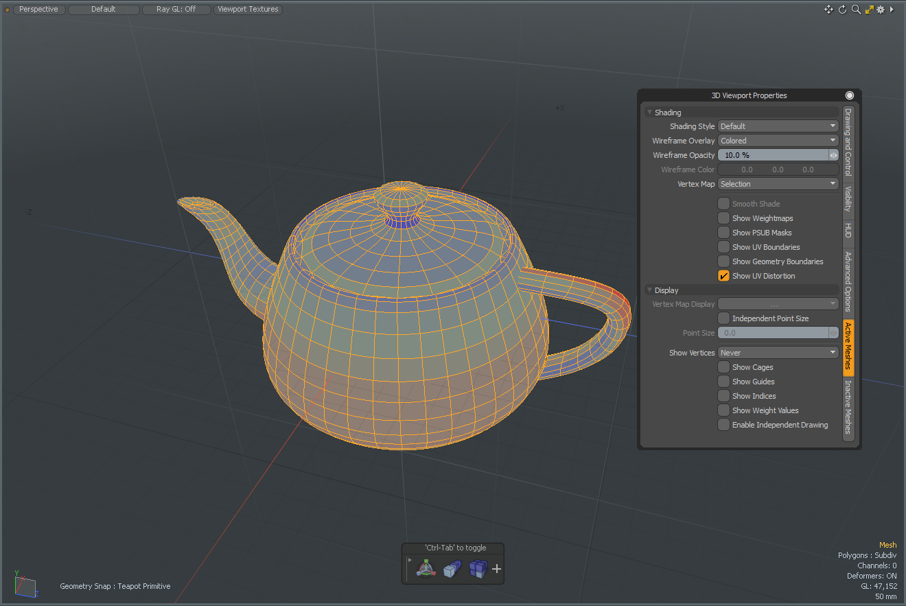
3D Viewport Properties: Active Meshes
The following options allow you to control the display of elements that are in the foreground, meaning they are selected in the Items list. Background layers are those that are visible, but not selected.
Shading
• Shading Style - You can choose from the available view styles covered above: Wireframe, Solid, Shaded, Vertex Map, Texture, Shaded Texture, Default, Advanced, Gooch, Cel and Reflection Shading.
• Wireframe Overlay - Determines the style of geometry wireframe display. You can adjust the colors of the wireframe using the preference setting in Windows in System > Preferences > Display > Colors and on Mac OS in Menu > Preferences > Display > Colors. Once a color scheme is created in the Preferences and saved as a named preset, it must be applied to the active viewport with the menu bar command View > Viewport Color Scheme.
• None - No wireframe displayed. (/)
• Uniform - By default this is a white wireframe outline. (Shift+/)
• Colored - By default this is a black wireframe outline. (Ctrl+/)
• Wireframe Opacity - Controls the opacity of the wireframe overlay display.
• Wireframe Color - Specifies the color of the wireframe in the 3D viewport.
• Vertex Map - Defines which type of Vertex Map is displayed when in the Vertex Map viewport.
• Selection - Displays the most recent Vertex Map selection.
• Weight - Favors Weight Maps for display.
• Vertex Color - Favors vertex color maps for display.
• Smooth Shade - This toggle overrides the material Smoothing setting, only changing how smoothing is displayed in the viewport, not the rendered output. When disabled, individual polygons shade flat, appearing faceted. When enabled, polygons shade according to the material Smoothing setting.
• Show Weightmaps - When enabled, selected Weight Maps are visible as overlays to the shaded elements in the 3D viewport in Default viewport display style. This includes the automatic weights associated with bones and deformers.
• Show PSUB Masks - Toggles the visibility of the sculpting masks in the viewport when working with multi-resolution sculpting. When a masks visibility is disabled, the mask still affects the target unless the Enable Mask option is inactive. For more information, see Using Sculpting Masks.
• Show UV Boundaries - Toggles visibility of UV boundaries in the 3D viewport. These display as thin purple lines overlaid on the surface, representing the outline of each UV island. The default color can be changed in the System > Preferences > Color options.
• Show Geometry Boundaries - Toggles visibility of Geometry boundaries. These display as a thin green line on any open edges of a surface. Especially useful in highlighting hidden surface discontinuities.
• Show UV Distortion - Toggles visibility of the colors displayed for the geometry with signifying distorted areas. Enabling this option displays a color overlay on the geometry, fading toward red when polygons are distorted and smaller (relative to other polygons in the map) and fading toward blue when they are distorted and larger (relative to other polygons). Polygons that are the closest relative size to others in the map with the least distortion display a middle gray/green color.
Show Locked Mesh Items - Displays locked polygons, edges, and vertices in the 3D viewport in a specified color. This option is enabled by default. For more information, see Locking.
Display
• Vertex Map Display - Sets which color component of the selected RGBA map is drawn in the Vertex map mode. The following options are available:
• RGB
• Alpha
• Red
• Green
• Blue
Note: The Shading > Shading Style must be set to Vertex Map to set the Vertex Map display.
• Independent Point Size - This is a per-viewport override for the display size of selected vertices. When enabled, you can specify the actual display size with the Point Size option.
• Point Size - Determines the display size of selected vertices when the Independent Point Size option is enabled. Values are in screen pixels.
• Show Vertices - Allows you to set visibility in the selected 3D viewport. The following options are available:
• Always - Always show vertices.
• In Component Modes - Only show vertices in Component mode.
• In Vertex Mode - Only show vertices in Vertex Component mode.
• Never - Never show vertices.
• Show Cages - Toggles the visibility of the Subdivision Surface Cage representation. This can be considered the original polygons that were smoothed.
• Show Guides - Toggles the visibility of guide lines that draw between the subdivision limit surface and the cage geometry.
• Show Indices - Toggles the visibility of the component index values display. Each number represents the particular component index. Visibility can be especially helpful when working with Geometry Constraints, where Constraints require specific index values for input.
• Show Weight Values - Toggles the visibility of Weight Map value display. A numeric value representing the current vertex weight amount displays next to each selected vertex in the 3D viewport. See Working with Vertex Maps for Weight Map usage information.
• Enable Independent Drawing - The Display Viewport allows you to define custom display options for each item layer. By default, the Enable Independent Drawing option is enabled and these custom drawing options display in all viewports. When enabled, all custom drawing options are ignored for active meshes.
3D Viewport Properties: Inactive Meshes
The following options allow you to control the display of item layers that are in the background, meaning that they are visible in the Items list, but unselected (not highlighted).
Overrides
• Make Inactive Same as Active - When enabled, this option overrides all settings of the Inactive Meshes options panel and all background item layers display as foreground elements.
• Make Inactive Invisible - When enabled, all item layers that are visible according to the visibility column of the Items list, but unselected don't show in the 3D viewport. This makes it easy to solo a single layer by simply selecting it without affecting the rendered image or requiring multiple layers' visibility to be toggled.
Shading
• Shading Style - You can choose from the available view styles covered above: Wireframe, Solid, Shaded, Vertex Map, Texture, Shaded Texture, Default, Advanced, Gooch, Cel and Reflection Shading.
• Wireframe Overlay - Determines the style of geometry wireframe display. You can adjust the colors of the wireframe using the preference setting on Windows and Linux in System >Preferences > Display > Colors and on Mac OS in Menu >Preferences > Display > Colors. Once a color scheme is created in the preferences and saved as a named preset, it must be applied to the active viewport with the menu bar command View > Viewport Color Scheme.
• None - No wireframe displayed. (/)
• Uniform - By default this is a white wireframe outline. (Shift+/)
• Colored - By default this is a black wireframe outline. (Ctrl+/)
• Wireframe Opacity - Controls the opacity of the wireframe overlay display.
• Wireframe Color - Defines which color to display.
• Vertex Map - Defines which type of Vertex Map is displayed when in the Vertex Map viewport.
• Selection - Displays the most recent Vertex Map selection.
• Weight - Favors Weight Maps for display.
• Vertex Color - Favors vertex color maps for display.
• Smooth Shade - This toggle overrides the material Smoothing setting, only changing how smoothing is displayed in the viewport, not the rendered output. When disabled, individual polygons shade flat, appearing faceted. When enabled, polygons shade according to the material Smoothing setting.
• Show Weightmaps - When enabled, selected Weight Maps are visible as overlays to the shaded elements in the 3D viewport in Default viewport display style. This includes the automatic weights associated to bones and deformers.
• Show PSUB Masks - Toggles the visibility of the sculpting masks in the viewport when working with multi-resolution sculpting. When a masks visibility is disabled, the mask still affects the target unless the Enable Mask option is inactive. For more information, see Using Sculpting Masks.
• Show UV Boundaries - Toggles visibility of UV boundaries in the 3D viewport. These display as thin purple lines overlaid on the surface, representing the outline of each UV island. The default color can be changed in the Color Preferences section.
• Show Geometry Boundaries - Toggles visibility of Geometry boundaries, These display as a thin green line on any open edges of a surface. Especially useful in highlighting hidden surface discontinuities.
• Show UV Distortion - Toggles visibility of the colors displayed for the geometry with signifying distorted areas. Enabling this option displays a color overlay on the geometry, fading toward red when polygons are distorted and smaller (relative to other polygons in the map) and fading toward blue when they are distorted and larger (relative to other polygons). Polygons that are the closest relative size to others in the map with the least distortion display a middle gray/green color.
• Apply Current Morph - When a Morph Map is selected, the Morph is applied to all visible meshes, in active layers and inactive layers. The Apply Current Morph option toggles the display of Morphs for background (inactive) layers.
Display
• Independent Point Size - This is a per-viewport override for the display size of selected vertices. When enabled, you can specify the actual display size with the Point Size option.
• Point Size - Determines the display size of selected vertices when the Independent Point Size option is enabled. Values are in screen pixels.
• Show Vertices - Toggles the visibility of unselected vertices (selected vertices are always visible, unless Show Selection is disabled).
• Show Cages - Toggles the visibility of the Subdivision Surface Cage representation. This can be considered the original polygons that were smoothed.
• Show Guides - Toggles the visibility of guide lines that draw between the subdivision limit surface and the cage geometry.
• Enable Independent Drawing - The Display viewport allows you to define custom display options per item layer. By default, these custom drawing options display in all viewports. However, when the Enable Independent Drawing option is enabled, all custom drawing options are ignored for active meshes.