Search is based on keyword.
Ex: "Procedures"
Do not search with natural language
Ex: "How do I write a new procedure?"
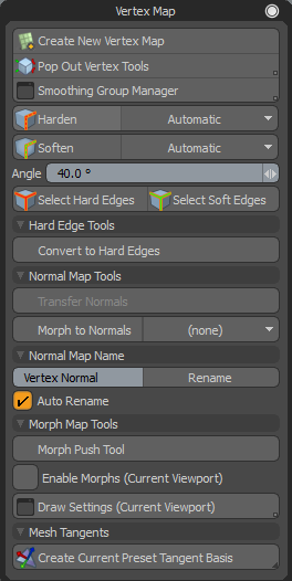
Vertex Normal Tools
Modo provides a set of tools for working with vertex normals. Use these tools to control the shading on the mesh using a system of hard and soft edges, as defined by vertex normals. Vertex normals provide an efficient way to smooth shade a polygon mesh, giving it the appearance of a much higher poly mesh. Vertex normal smoothing provides much more control over edge hardness than material smoothing. You can use these tools to gain more control of vertex normals and edge smoothing while creating art used for game engines.
Often when you are working on a low resolution model, you may end up with shading errors on hard angles creating artifacts. You can set options to calculate the normals, and use smoothing groups for blending to resolve such problems.
You can use the Vertex Map tools to quickly select hard or soft surfaces and edit an existing vertex map. If none exists, one is automatically added that holds the normals for the entire mesh. You can then select edges and edit the map as required. The vertex map is automatically updated if you alter the mesh and the map is recalculated for the updated normals on your mesh.
Opening the Vertex Normal Tools
The Vertex Normal tools can be found in the following locations:
• From the menu bar, click Vertex Map > Vertex Normal Tools....
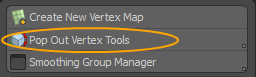
Tip: You can work with a smaller sub-set of these tools. For more information, see Using the Pop Out Vertex Tools.
• Alternatively, open the Game layout and open the Vertex Map tab on the left panel.
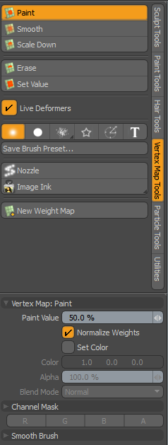
• If you want to adjust vertex color maps and vertex weight maps, open the Paint layout. On the left panel, open the Vertex Map Tools sub-tab, and click Paint. For more information, see Vertex Map Paint.
Creating a New Vertex Map
Vertex maps provide functions for modeling, shading, and rendering. These maps work in tandem with the smoothing and hardening functions to shade polygons. You can create a new vertex map, provide a unique name for the map, and set an initial value. Once created, the named map immediately appears within the appropriate section of the Lists viewport.
| 1. | On the Vertex Map dialog, click Create New Vertex Map. |
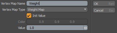
| 2. | Edit the fields and click OK. |
For more detailed information about these options, see Create New Vertex Map.
Note: You can apply smoothing options to an existing Material. Vertex normals are calculated as part of Modo's native smoothing and they update as geometry is edited and when applied deformers change the mesh item.
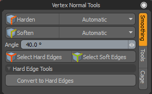
Using the Pop Out Vertex Tools
You can use a small palette of vertex normal tools, which provides easy access to common tools used for smoothing, normal maps, and cage options. From this palette you can select several different types of geometry to apply changes.
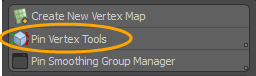
| 1. | On the Vertex Map dialog, click Pop Out Vertex Tools. |
Alternatively, press Alt and click Pin Vertex Tools.
This opens a small tool palette.
Using the Smoothing Group Manager
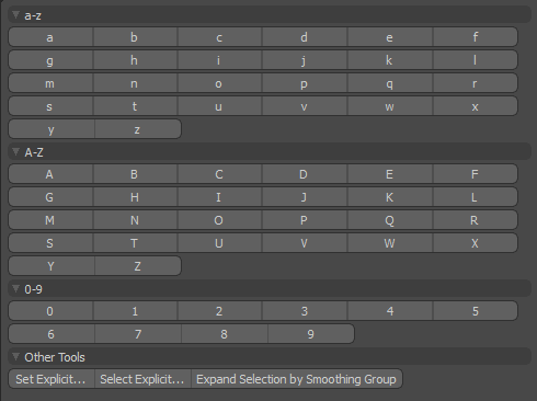
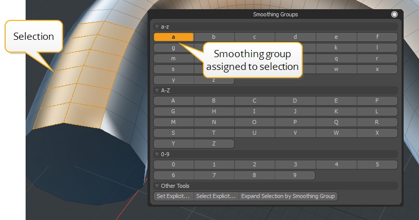
Modo allows you to group geometry and create polygon set smoothing groups to target smoothing areas. This tool is designed to ease your workflow when working on complex models. This is especially true in the case of lower resolution game models where you might prefer to set smoothing based on groups. Smoothing groups are assigned alphanumeric characters (A-B, 0-9) representing sets. Imported models using smoothing groups display highlighted letters and numbers in the Smoothing Group palette for specified smoothing groups.
Launching the Smoothing Group Manager
On the menu bar, click Vertex Map > Vertex Normal Tools... and then click Smoothing Group Manager.
Alternatively, on the menu bar, click Geometry > Polygon > Open Smoothing Group UI....
Creating Smoothing Groups
Select the desired polygons and click a letter(s) and number(s) to assign them to a Smoothing Group. The letter/number displays in orange to indicate that the smoothing group was created. All of the selected polygons are smoothed together.
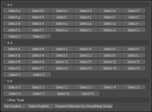
Selecting Polygons Assigned to a Smoothing Group
Press Alt and click an assigned group. The assigned polygons are selected on your mesh item.
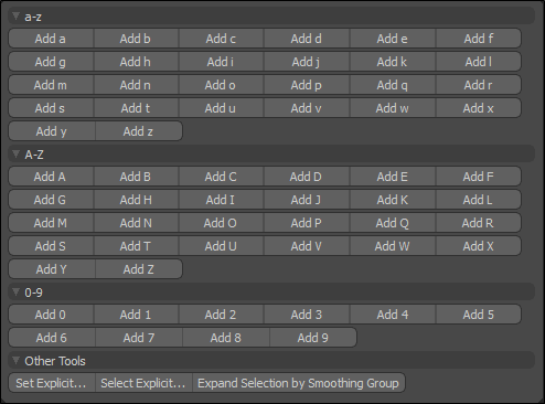
Assigning Polygons to an Existing Smoothing Group
Select additional polygons on your mesh item, hold Shift, and click an assigned smoothing group. All of the polygons are assigned to this smoothing group..
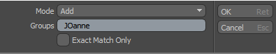
Alternatively, if you have a unique smoothing group name, click Select Explicit..., set Mode to Add, and enter the unique smoothing group name in the Group field. The selected polygons are added to that group.
Removing Polygons From a Smoothing Group
| 1. | Select the polygons you want to remove from the smoothing group. |
In the Smoothing Groups manager, the active smoothing group(s) for the selection are highlighted in orange.
| 2. | Click the letter/number of the smoothing group you want to remove. |
The smoothing group is no longer highlighted and smoothing is removed from the selected polygons.
Blending Smoothing Groups
You may want to blend a selection of polygons in a smoothing group with another smoothing group to create a soft edge where the smoothing groups meet. In order to do that, you need to create more than one smoothing group.
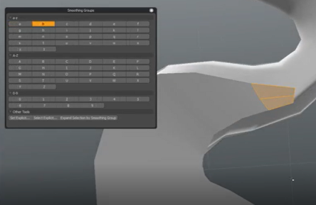
| 1. | Make a polygon selection, click the letter(s)/number(s) for the smoothing group it is assigned to. In this example, I have clicked a. |
The selection of polygons are removed from the assign smoothing group and hard edges are created.
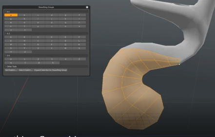
| 2. | Assign a new smoothing group by clicking on another unused letter(s)/number(s). In this example I have assigned these selected polygons to the smoothing group b. |
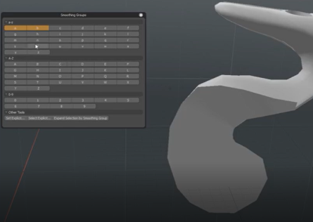
| 3. | Click in the 3D viewport to deselect those polygons. |
The letter buttons a and b fades out to tell you that there are multiple smoothing groups used by this selection.
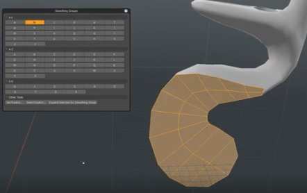
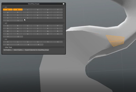
| 4. | Next, select an area of polygons in the newly created smoothing group to blend. In this example, I have selected the top polygons in the smoothing group b. |
| 5. | Select the smoothing group letter(s)/number(s) you want to blend your selection with. In this example, I have selected the smoothing group a. |
The polygons are blended into the selected smoothing group. Both a and b smoothing groups display in orange in the Smoothing Groups window.
Working with Explicit Smoothing Groups
You can add, remove, set, or expand a new selection of polygons to an explicit set. This is useful when you have imported a model containing pre-assigned smoothing groups using explicit names.
| 1. | Select the polygons you want to explicitly apply to a smoothing group and click Select Explicit.... |
This opens the select by smoothing groups window.
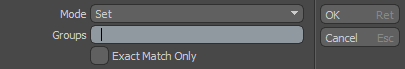
| 2. | From the Mode dropdown menu, select one of the following: |
• Set - Sets the current selection of polygons to the specified group. Previously smoothing group polygons are overwritten.
• Add - Adds the current selection of polygons to the specified group.
• Remove - Removed the current selection of polygons from the specified group.
• Expand - Selects all the other polygons on your mesh and deselects the current selection. You can then specify a smoothing group.
| 3. | In the Name field, type the name of the unique smoothing group name. |
| 4. | Optional - Enable Exact Match Only to locate smoothing groups matching the capitalization you have specified. |
Setting Hard and Soft Edge Smoothing Options
The Vertex Normal Tools allow you to harden or soften selected geometry. The vertex map is automatically updated if you alter the mesh and the map is recalculated for the updated normals on your mesh.
To apply softer or harder normals to a selection of edges:
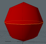
| 1. | Select edges of your mesh item and click Harden or Soften. |
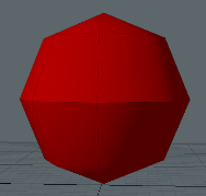
• Harden - The hard edges split the smoothing of vertex normals across them and produce sharp edges.
|
|
|
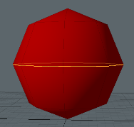
Softened edge mesh with central edges selected. |
Selected edges have been hardened. |
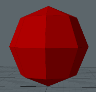
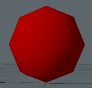
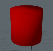
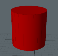
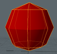
• Soften - Soft edges are applied to the selection of vertex normals and produce a unified smooth surface.
|
|
|
A mesh without smooth shading. |
All edges have been softened. |
| 2. | From the drop-down menu, select the type of geometry to apply. The following options are available: |
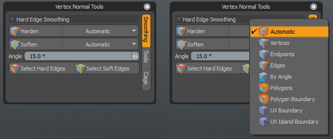
• Automatic - Automatically uses vertices, edges, or polygons mode depending on the current selection mode.
• Vertex - Hardens or softens all edges connected to the selected vertices. Shift+click to harden or soften all edges connected to any of the selected vertices.
• Endpoints - Hardens or softens only the edges that have both end vertices selected.
• Edges - Hardens or softens the selected edges.
Note: Hard edges are stored in an edge pick map called HardEdges. If no vertex map is present, and one edge is added, all other edges are soft. If you soften any hard edges, the affected edges are removed from the HardEdges map.
If you soften edges and there is no Vertex Map active on the mesh, a new vertex map is calculated for all normals, effectively smoothing the entire mesh.
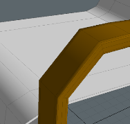
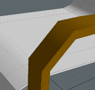
• By Angle - If hardening, hardens edges which are sharper than the given angle. If softening, soften edges are shallower than the given angle. This is useful for avoiding smoothing at hard edges, such as right angles.
|
|
|
A chair mesh with soft edges. |
All edges at seams sharper than 60° have been hardened. |
Note: Harden the smoothing across all selected edges that are between polygons at a sharper angle than the specified value (the Smoothing Angle). If no edges are selected, all edges are evaluated. Edit the Smoothing Angle before applying the By Angle command. You can change the Smoothing Angle and click the button to add hard edges to the HardEdges selection set. However, modifying the Smoothing Angle and hardening, does not remove any hard edges that were added as a result of prior operations.
• Polygons - Hardens or softens the edges on the boundary of the current polygon selection, softening the internal edges.
• Polygon Boundary - Hardens or softens the edges on the boundary of the current polygon selection (leaving the internal edges untouched).
• UV Boundary - If hardening, harden edges which lie on the boundary of the current UV map. If softening, soften edges which lie on the interior of the current UV map islands.
|
|
|
Mesh with all soft edges. |
Edges at UV boundaries have been hardened. |
• UV Island Boundary - If hardening, hardens edges which belong to multiple UV islands. If softening, soften edges which only belong to one UV island. (A UV island is a connected group of polygons in a UV map.)
Procedural Hard Edges
The Hard Edges tool is also available as a mesh operation.
Tip: For more information on procedural modeling and mesh operations, see Procedural Modeling.
To use the mesh operation:
| 1. | Select the edges to modify. |
| 2. | In the Mesh Ops tab, click Add Operator. |
Tip: If the Mesh Ops tab is not visible on the right panel, click the + button on the right of the tab names, and select New Tab > Data Lists > Mesh Ops.
| 3. | Under Mesh Operations > Edit, double-click Hard Edge. |
The selected edges are hardened and the operation is added to the Mesh Operations list.
The Hard Edge mesh operation's properties are displayed in the lower right panel, in the Properties tab.
• You can change what Selection Type the Automatic Mode should use.
• To harden the edges, Hardness should be set to Hard. To soften, set it to Soft.
• The Mode options are the same as for the direct modeling equivalent.
• Enabling Clear Other Hard Edges removes any existing hard edges before running the operation.
• Angle specifies the angle value for Angle Mode, and UV Map specifies what map is used when Mode is set to UV Boundary or UV Island Boundary.
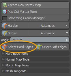
Selecting Hard Edges
The Select Hard Edges tool allows you to select all edges marked as hard. Hard edges are stored in the HardEdges map.
| 1. | Click Vertex Map > Vertex Map Tools... |
| 2. | On the Vertex Map dialog, click Select Hard Edges. |
Alternatively, use the following keys to add or remove hard edges from your current selection.
• Shift+click Select Hard Edges to add all hard edges to the current edge selection.
• Ctrl+click Select Hard Edges to remove all hard edges from the current edge selection.
Procedural Select Hard Edges
There is a procedural selection operation for selecting hard or soft edges. For more information, see Select by Pattern.
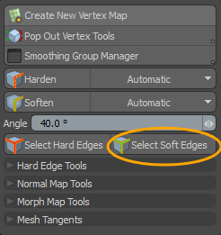
Selecting Soft Edges
The Select Soft Edges tool allows you to select all edges not marked as hard. This is all edges except those stored in the HardEdges map.
| 1. | Click Vertex Map > Vertex Map Tools... |
| 2. | On the Vertex Map dialog, click Select Soft Edges using one of the following: |
Alternatively, use the following keys to add or remove hard edges from your current selection.
• Shift+click Select Soft Edges to add all edges not marked as hard to the current edge selection.
• Ctrl+click Select Soft Edges to remove all edges not marked as hard from the current edge selection.
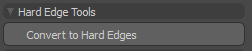
Converting to Hard Edges
Marks any edge which has its shading split at either end (or both ends) as a hard edge. Optionally, it removes all smoothing groups and vertex normal maps after marking the relevant edges as hard.
| 1. | In the Vertex Map dialog, under Hard Edge Tools, click Convert to Hard Edges. |
| 2. | In the Convert to Hard Edges dialog, select one of the following: |
• Clear Smoothing Groups
• Remove Normal Maps
Procedural Hard Edge Convert
The Hard Edge Convert tool is also available as a mesh operation. This operation converts the selected edges that are split by smoothing groups or vertex normal maps to Modo's Hard Edges system. It can be useful when importing CAD scenes that include vertex normal maps.
Tip: For more information on procedural modeling and mesh operations, see Procedural Modeling.
To use the mesh operation:
| 1. | Select the edges to modify. |
| 2. | In the Mesh Ops tab, click Add Operator. |
Tip: If the Mesh Ops tab is not visible on the right panel, click the + button on the right of the tab names, and select New Tab > Data Lists > Mesh Ops.
| 3. | Under Mesh Operations > Edit, double-click Hard Edge Convert. |
The selected edges are hardened and the operation is added to the Mesh Operations list. The mesh operation's properties are displayed in the Properties tab in the lower right panel. After applying the operation, you can delete any existing normal maps or smoothing groups by enabling Remove Normal Map or Remove Smoothing Group.
Transferring Normals from another Mesh Shader
You can copy a vertex normal map from a background mesh using the Transfer Normals button. For example, you may want to use the shading from a higher resolution mesh on other mesh items. The normals are copied from the background mesh to the active foreground mesh.
The transfer works by finding the closest (by distance) vertex-polygon pair on the background mesh to each vertex-polygon pair on the foreground mesh, and copies the normal value over. Once done, the normals themselves can be moved apart, rotated, and scaled in Items selection mode.
![]()
| 1. | Select the foreground mesh. |
Note: Make sure the background mesh (or the layer directly below the active layer in the Items list when there are multiple item layers) is marked as visible (![]() ) and unselected in the 3D viewport.
) and unselected in the 3D viewport.
| 2. | In the Vertex Map dialog, click Transfer Normals. |

|
|
|
Two mesh items. |
The Vertex Normals have been copied from the right mesh to the left mesh. |
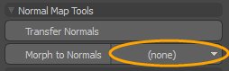
Applying Morph to Normals
For each selected vertex, Morph to Normals takes the direction of the offset defined in the currently selected Relative Morph Map, and sets the vertex normal to point in that direction. The vertex position offset is relative to the base vertex position. If the offset has zero length, or the value is unset in the morph map, the normal is unchanged.
For more information, see Working with Vertex Maps and Set Vertex Normals.
| 1. | In the Vertex Map dialog, click the down arrow and select a morph map from the dropdown list. |
| 2. | If you do not have a Morph Map, click (new) and specify the options. |
For more information, see Create New Vertex Map.
| 3. | In the Vertex Map dialog, click Morph to Normals. |
Renaming the Normal Map
The default name for the calculated Vertex Normal Map is Vertex Normal.
| 1. | To rename it, edit the name and click Rename. |
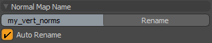
| 2. | Check Auto Rename to automatically assign the given name to the vertex normal map after updating smoothing on a mesh item. |
Using the Morph Push Tool
When baking normals, you can use a morph map as a cage to determine the offset distance for the rays. The Morph Push Tool lets you alter the cage size to customize the results of a bake. It also provides a more flexible alternative to Modo's Push tool for deforming morph maps.
Note: For more information on using Cages, see Bake from Object to Selected Texture
Compared to the Push tool, the Morph Push Tool has the following additional features:
• It always computes high quality normals to push along.
• It uses angle-weighted normals.
These features ensure a cleaner push, with no discrepancies from non-planar polygons or differently triangulated meshes.
The images below shows the Morph Push Tool used to create a cage for a low-poly mesh prior to baking.
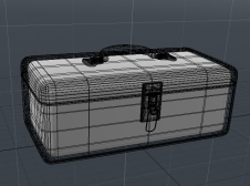
|
A foreground high poly mesh of a toolbox above a low poly mesh (selected). The low poly mesh also has an empty Morph Map. |
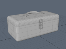
|
The two meshes as viewed in Game mode. |
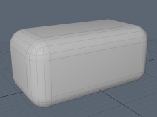
|
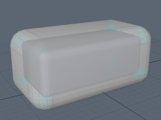
The Morph Map on the low poly mesh has been pushed using the Morph Push Tool to create a suitable Cage. |
To apply the Morph Push Tool:
| 1. | On the Vertex Normals dialog, click Pop Out Vertex Tools. |
Alternatively, hold Alt and click Pin Vertex Tools
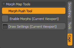
| 2. | In the Vertex Normal palette, open the Cage tab, and click Morph Push Tool. |
| 3. | Click in the 3D viewport to apply the tool. |
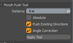
| 4. | On the left panel, edit the parameters as required, and click Apply Tool. |
|
Distance |
The distance to push the morphed position of each vertex. Tip: Click and drag in the 3D viewport to adjust the Distance. |
|
Absolute |
This makes the distance value absolute, rather than relative. Enable this to ensure that the distance each vertex is pushed is uniformly set to equal the Distance value, regardless of the distance that was already defined in the Morph Map. |
|
Push Existing Directions |
When checked, this ensures that the direction of the existing morph is used when pushing the vertices (instead of the default average normal). |
|
Angle Correction |
Enable this to retain the form of the mesh as best as possible when pushing. When enabled, the vertices on flat planes are pushed out by the Distance amount, while vertices on corners are pushed out more, to compensate for the averaged normal. |

|
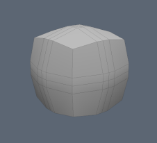
|
|
|
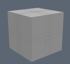
A 1m cube with an empty Morph Map. |
The cube has been pushed by 1m without Angle Correction. |
The same 1m push but with Angle Correction. |
Other Morph 3D Viewport Options
|
Enable Morphs (Current Viewport) |
Allows the 3D Viewport to display the results of animated morphs. Enabling this option disables deformers. |
|
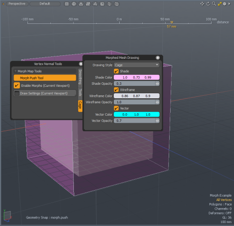
Draw Settings (Current Viewport) |
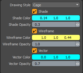
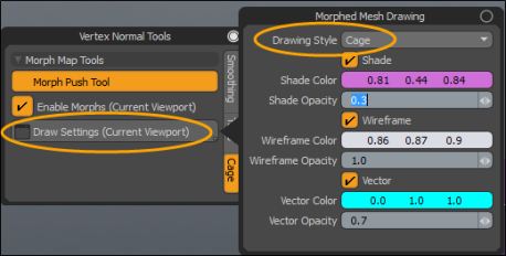
Specifies how you would like to draw Morph Maps. The following options are available when enabled: Drawing Style - Specify how you would like to draw Morph Maps. The following options are available: • Default - Modo draws the traditional morphed mesh. • Cage - Modo draws the base mesh and the morphed mesh as a cage. When this option is selected, additional properties are revealed:
Shade - When enable, draws a transparent morphed mesh as a cage. Shade Color - Specifies the color of the morph cage. Note: Only displayed when a Shader, Wireframe, or Vector is enabled. Shade Opacity- Specifies the opacity value of the morph cage. Wireframe - Draws the cage in wireframe mode. Wireframe Color - Specifies the color of the wireframe. Wireframe Opacity - Specifies the wireframe opacity. Vector - Draws line segments from the vertices of the base mesh to the corresponding vertices of the morph mesh. Vector Color - Sets the vector color. Vector Opacity - Sets the vector opacity. To display a morphed mesh, you need to select a morph map with Enable Deformers disabled. |
Viewing the Morph Maps Cage View
You can quickly see the difference between an original mesh and the morphed version using the Cage view. This is useful for viewing morph maps that are used as cages for baking.
For more information on using Cages, see Bake from Object to Selected Texture
Enabling the Cage View
To enable Cage View, you must first configure the 3D viewport Properties.
| 1. | Hover the mouse over the 3D viewport, press O to open the 3D viewport Properties. |
| 2. | Open the Drawing and Control tab, under the View and Shading section, enable Overlay Drawing. |
| 3. | Under the Animation section, disable Enable Deformers. |
To view a cage:
The following is a simple workflow example viewing the cage for a morph map applied to a cube primitive.
| 1. | On the left panel of the Model layout, press Ctrl/Cmd and click the Cube |
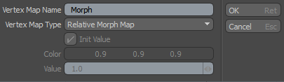
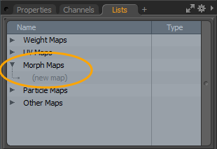
| 2. | On the right panel, open the Lists tab, expand Morph Maps > Morph, and click (new map). |
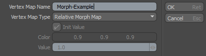
| 3. | In the Create New Vertex Map dialog, enter a new name, set Vertex Map Type to Relative Morph Map, and click OK. |
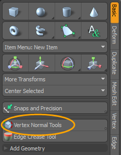
| 4. | On the left panel, in the Basic tab, click Vertex Normal Tools. |
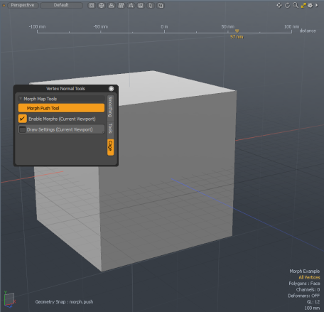
| 5. | In the Vertex Normal Tools palette, click Morph Push Tool, and click-and-drag in the 3D viewport. |
| 6. | Click Draw Setting (Current Viewport) and set Drawing Stye to Cage. You can also set the other options if desired. For more information, see Other Morph 3D Viewport Options. |
The original, unmorphed mesh is overlaid on the current geometry, and dashed lines are drawn between the unmorphed mesh and the morphed mesh.
Creating Mesh Tangent Maps
You can create tangent basis maps for various renderers using the Mesh Tangents options.
Tip: A number of Mesh Tangent options are also available from the Vertex Map > Tangent Vectors menu.
Note: If no UV maps are selected, the commands iterate over all active meshes, and tangent basis maps are generated for all UV sets on each active mesh.
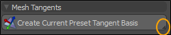
| 1. | On the Vertex Normal dialog, on the Create Current Preset Tangent Basis button, click the dropdown arrow. |
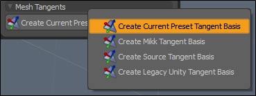
| 2. | Select one of the following options. |
Note: The default preset is called None, and the default label for the button is Create Current Preset Tangent Basis. Changing the normal map preset changes the label.
• Create Current Preset Tangent Basis - Create a tangent basis map using the tangent command that is defined in the current normal map preset used in the Game Asset Exporter. See Editing Presets for how to choose and edit normal map presets for a project.
• Create Mikk Tangent Basis - Creates a tangent basis map using Mikk Tangent Space.
• Create Source Tangent Basis - Creates a tangent basis map compatible with Valve's Source engine.
• Create Legacy Unity Tangent Basis - Creates a tangent basis map compatible with the Unity Engine's legacy tangent basis standard.
Tip: A full list of tangent basis map generation commands can be found in the Game layout, Export & Presets toolbox tab, under the Edit Normal Map Preset... option. For more information, see Game Asset Exporter.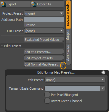
Sorry you didn't find this helpful
Why wasn't this helpful? (check all that apply)
Thanks for your feedback.
If you can't find what you're looking for or you have a workflow question, please try Foundry Support.
If you have any thoughts on how we can improve our learning content, please email the Documentation team using the button below.
Thanks for taking time to give us feedback.