Search is based on keyword.
Ex: "Procedures"
Do not search with natural language
Ex: "How do I write a new procedure?"
Merge Meshes
The Merge Meshes tool merges multiple mesh layers into a single procedural mesh. You can also apply Merge Meshes to direct modeling mesh items to create a single mesh.
Courtesy William Vaughan
Use the Merge Meshes tool to:
• Copy any item into a procedural layer.
For example, the source geometry can be a MeshFusion item, the procedural mesh, VDB voxels, or one of the other procedural items. Once merged, you can modify or deform the procedural result like any other procedural mesh.
Note: The geometry type (triangles or quads) is dependent on the geometry provided by the procedural surface. No post-processing is done to clean up or modify the geometry in any way.
• Use the Merge Meshes tool as a mesh operator to control which properties are merged.
For example, you can read replicator items as geometry inputs allowing replicated geometry to be manipulated using procedural modeling tools. These replicator items can be exported as a single mesh item to use in other projects. For more information, see Using the Merge Meshes Operator
• Apply the Merge Meshes operation to a group item. For more information, see Applying Merge Meshes to a Group.
• Use Merge Meshes to convert a particle simulation into vertices in a mesh layer. You can then use deformers to modify the simulation.
Note: If you modify the source mesh, your changes are also applied to the target mesh. However, the changes you make to the mesh in the target layer are not carried over to the source mesh. Deleting the original mesh also removes the mesh from the target layer.
Merging Meshes
| 1. | On the right panel, open the Items list and select the item layers to merge. |
| 2. | Right-click and select Merge Meshes, |
The Merge Meshes dialog displays with the Transform Compensation option enabled. This option transforms the normal map values to correspond to the new vertex positions in the merged mesh.
![]()
| 3. | Click OK. |
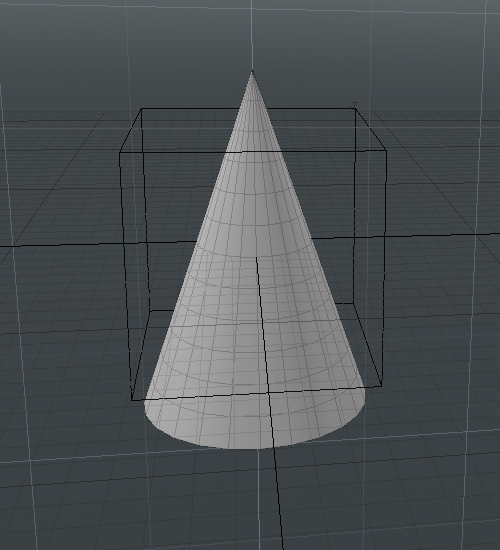
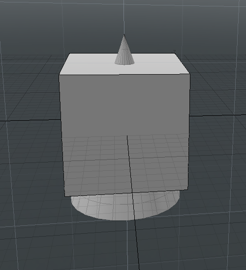
All mesh layers in your scene are merged into the target parent mesh. No vertices are merged.
|
|
|
|
The target mesh in the 3D viewport before the Merge Meshes operation. |
The target mesh in the 3D viewport after the Merge Meshes operation. |
Applying UnMerge Meshes
| 1. | On the right panel, open the Items list. |
| 2. | Right-click on a parent mesh item and select UnMerge Meshes. |
All the separate mesh items within a single parent mesh item are created as individual mesh items.
Using the Merge Meshes Operator
Use the Merge Meshes mesh operation to specify which Merge Meshes Properties are merged.
You can apply Merge Meshes to:
• selected items
• a parent item
or
• group item
| 1. | Open the Mesh Ops tab and click Add Operator. |
Tip: If the Mesh Ops tab is not visible on the right panel, click the More Tabs or New Tab icon and select New Tab > Data Lists > Mesh Ops.

| 2. | Navigate to Mesh Operations > Edit and double-click Merge Meshes. |
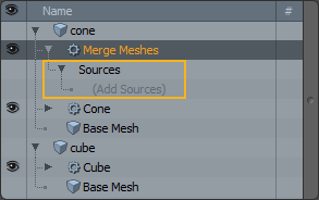
| 3. | Expand the Merge Meshes operator and click (Add Sources). |
| 4. | Navigate to Modifier Mesh Operations > Existing and select the parent source mesh item. |
Tip: When specifying the (Add Sources) value, you can also select Modifier Mesh Operations > New > Particles > Replicator. The replicator items are converted to geometry items and you can continue applying various procedural operations to modify each layer. Once done, right-click Merge Meshes and select Freeze and then export your selection (File > Export As...). For more information, see Replicators.
| 5. | In the Properties panel, on the bottom of the Mesh Ops tab, enable Merge Hierarchy. |
Partial Merges
Merge Meshes can perform partial merges, allowing certain mesh elements to be skipped. This is useful when merging surfaces that contain normal maps, as the presence of the normal map is often undesirable for further edits.
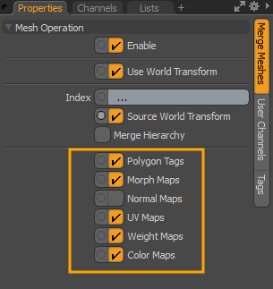
In the Merge Meshes Properties tab, on the right panel, enable or disable the following channels:
Applying Merge Meshes to a Group
Once the Merge Meshes tool is applied to a group, you can later add other items to that group. The Merge Meshes tool controls all items added to a group.
Tip: To add an item to an existing group, select it in the 3D viewport and open the Groups tab on the right panel. Right-click on the group item and select Add Item from the contextual menu. For more information, see Groups Viewport.
| 1. | In the Model layout, open the Items tab, and select the mesh items to group. |
| 2. | On the right panel, open the Groups tab, and click New Group. |
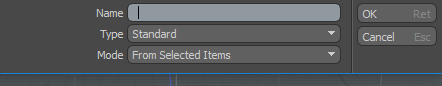
| 3. | Enter a meaningful Name and click OK. |
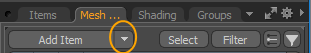
| 4. | Open the Mesh Ops tab, click the down arrow beside Add Item and select Mesh. |
| 5. | Click and drag this mesh layer and move it to the top of the list. |
| 6. | Click Add Operator, expand Mesh Operations > Edit, and double-click Merge Meshes. |
| 7. | Expand Merge Meshes > Sources, and click (Add Sources). |
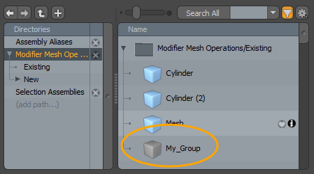
| 8. | In the Add Operator dialog, expand Modifier Mesh Operations > Existing and double-click My_Group. |
Applying Merge Meshes to Text
You can use the Index option to specify which Text mesh items to include in a Merge Meshes operation.

Note: For more information about the Text primitive, see Text.
| 1. | In the Model layout, open the Mesh Ops tab, click Add Item, and double-click Locators > Mesh. |
| 2. | On the right panel, click Add Operator, expand Mesh Operations > Create > Primitives, and double-click Text. |
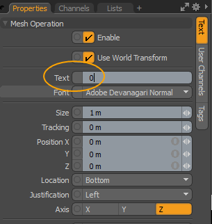
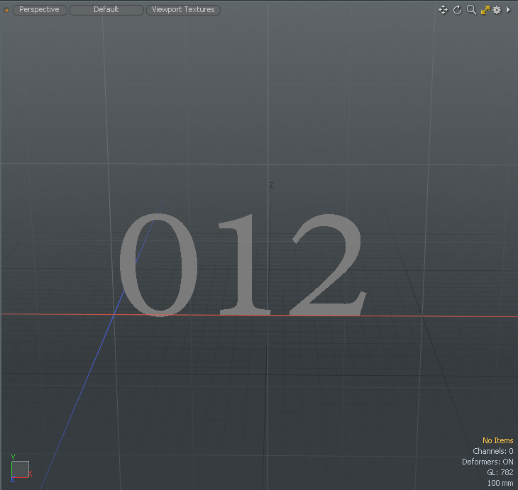
| 3. | In the Properties tab, on the bottom right panel, enter in a number into the Text field. |
| 4. | Select the Text primitive, press W, and drag the text field into an new position along the X axis. |
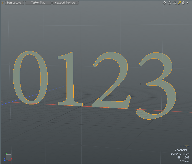
| 5. | Repeat steps 1 - 4 to add the four separate text meshes to your scene, such as 0, 1, 2, and 3. |
Tip: To keep organized, double-click on each mesh item in the Items list and type a new name.
| 6. | Click Add Operator, expand Mesh Operations > Edit, and double-click Merge Meshes. |
| 7. | Expand Merge Meshes > Sources, and click (Add Sources). |
| 8. | In the Add Operator dialog, expand Modifier Mesh Operations > Existing and select all of the mesh items you previously created. |
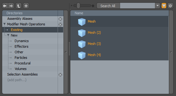
Warning: If you're trying to select your active mesh, Modo displays an error message.
| 9. | Drag-and-drop your selection onto the Merge Meshes Sources field. |
| 10. | In the Mesh Ops tab, click the |
The merged mesh items remain displayed in the 3D viewport.
| 11. | Select the Merge Meshes item, and type the 0-2 value in the Index field and press Enter. |
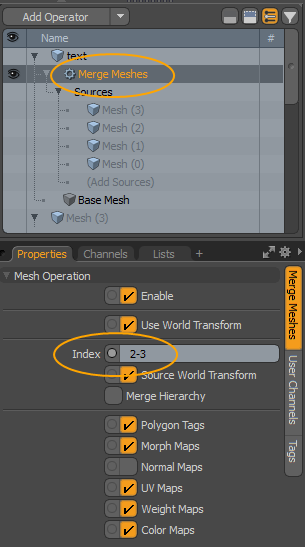
Note: The mesh items are numbered based on the order they were created, starting at 0 for the first item created.
Only the first three mesh items are displayed in the viewport.
Applying Merge Meshes to Particle Simulations
The Merge Meshes operation also works with particles. You can specify any kind of Particle Simulation as the Source of the operation, and it converts particle sources to vertices in a mesh layer. You can then apply deformers to the simulation.
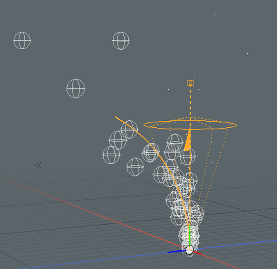
To merge your particle simulation into a mesh layer:
| 1. | Have a scene with a particle simulation and a mesh layer set up. |
Tip: To learn how to set up a particle simulation, see Particles and Simulations.
| 2. | In the Mesh Ops tab go to your mesh layer and click Add Operator. |
This opens the Add Operator dialog.
| 3. | Click Mesh Operations > Edit, and double-click Merge Meshes. |
The Merge Meshes operation is added to the Mesh Operations list.
| 4. | Expand Merge Meshes in the Mesh Operations list to reveal its Sources input. |
| 5. | Click Add Sources, and under Existing, double-click your particle simulation. |
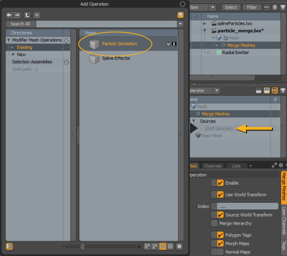
This merges the particle simulation to the mesh layer. The particles are converted to vertices that you can deform.
To deform the simulation:
| 1. | In the Mesh Operations list, add a deformer, for instance, a Bend Effector, and set it up in your scene. |
Note: For details on the various types of effectors and how to use them, see Applying Deformers.
| 2. | If you're using a Volume item, select the it to open its Properties on the right. |
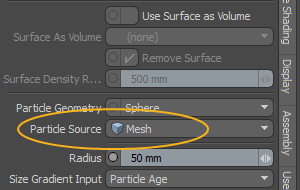
| 3. | In the Volume Particles sub-tab, under Geometry, set Particle Source to the mesh layer to which your simulation was merged. |
When you play the simulation now, the particles are deformed by the deformer you've added.
Merge Meshes Properties
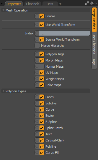
| Enable | Toggles merged meshes on and off. |
|
Use World Transform |
When enabled, the mesh operation maintains the world space on the input layer. |
| Index |
Specify the geometry to merge. Note: The mesh items are numbered based on the order they were created, starting at 0 for the first item created. For example: ... - All mesh items are merged. 1 - Only the second Merge Meshes Source mesh item is merged. 1... - The second and remaining Merge Meshes Source mesh items are merged. 1-3 - The second, third, and forth Merge Meshes Source mesh items are merged. |
| Source World Transform | Input items are merged using their world space. |
| Merge Hierarchy | Input items and all child items are merged. |
| Polygon Tags |
When enabled, merges polygon tags. For more information, see Polygon Set Material/Part/Smoothing. |
| Morph Maps |
When enabled, merges morph maps. For more information, see Morph Influence. |
| Normal Maps |
When enabled, merges normal maps. For more information, see Vertex Normal Maps. |
| UV Maps |
When enabled, merges UV Maps |
| Weight Maps |
When enabled, merges Weight Maps. |
| Color Maps |
When enabled, merges Color Maps. |
Merge Mesh - Polygon Types Properties
Use the following options to specify what type of polygons you want to extract from a mesh.
|
Faces |
Copy face polygons from the source mesh to the procedural mesh. A face polygon creates a faceted surface. An individual polygon is commonly called a face, which is bounded by three or more vertices and their associated edges. When many faces are connected together to create a network of faces, it's called a polygon mesh. |
|
Subdivs |
Copy subdivision patches from the source mesh to the procedural mesh. Subdivs are subdivision surface smoothed polygons. Subdividing polygons recursively splits the selected polygons into smaller polygons. For more information, see SDS Subdivide. |
|
Curve |
Copy curve polygons from the source mesh to the procedural mesh. For more information, see Adding Curves. |
|
Bezier |
Copy Bezier polygons from the source mesh to the procedural mesh. For more information, see Bezier. |
|
B-Spline |
Copy B-Spline polygons from the source mesh to the procedural mesh. B-Spline polygons are spline curves defined by at least four vertices and a Weight Map. For more information, see B-Spline. |
|
Spline Patch |
Copy spline patches from the source mesh to the procedural mesh. Spline patches produce a spline patch curve for further patching. This requires 3 or 4 vertices. For more information, see Patch Curves. |
|
Text |
Copy text polygons from the source mesh to the procedural mesh. Text polygons contain metadata in the form of polygon tags that store all the information about the font used, size, kerning amount, and so on. For more information, see Text. |
|
Catmull-Clark |
Copy Catmull-Clark patches from the source mesh to the procedural mesh. Catmull-Clark patches are Pixar Catmull-Clark smoothed polygons. For more information, see Set Polygon Type. |
|
Polyline |
Copy line polygons from the source mesh to the procedural mesh. A polyline is a continuous line composed of one or more line segments. For more information, see Line. |
|
Curve Fill |
Copy curve fill polygons from the source mesh to the procedural mesh. Curve fill polygons are closed, non-intersecting curves with quadrangles. For more information, see Curve Fill. |
Sorry you didn't find this helpful
Why wasn't this helpful? (check all that apply)
Thanks for your feedback.
If you can't find what you're looking for or you have a workflow question, please try Foundry Support.
If you have any thoughts on how we can improve our learning content, please email the Documentation team using the button below.
Thanks for taking time to give us feedback.