Projections in the New 3D System
Projecting Textures onto Objects
You can use the GeoProjectUV and Project3DShader nodes to project texture images onto your 3D objects. This way, you can add detail, surface texture, or color to your geometry, making the geometry more realistic and interesting. The GeoProjectUV node changes the UV values of the vertices whereas the Project3DShader node is a material shader.
|
Notes if you've used the Classic 3D System: |
|
Workflow wise, GeoProjectUV is very similar to the UVProject node in the Classic 3D System, and most of the knobs are the same. There are however a few knob updates for better USD compatibility and updated properties ordering, for example: • Cull Behind Projection Source allows you to stop any projections occurring behind the projection plane. • The attrib name knob from the classic node, has been updated to include a Generate Perspective knob which generates an ‘stw’ attribute containing the perspective (w) component of the uv and the Attribute Name allows you to specify the name for this. • Reference Frame essentially allows you to perform sticky projections. By enabling this knob the projection will only be applied at the frame being referenced, making it easy to set up projections that stick to moving prims. Note: GeoProjectUV projects onto vertices so the tessellation of the mesh is important especially when viewing in 3D Viewer as the standard texture mapping in Storm, especially with UsdPreviewShader, does not handle perspective projections and so you see distortions across a surface with large triangles/quads. The smaller the triangle/quad, the more vertices are projected on and the lower the visible distortion. The Project3DShader node has the same behavior of the classic Project3D node, but with two additional knobs with the ability to clip the projection beyond the cameras near and far planes. |
Projecting Textures with the GeoProjectUV Node
The GeoProjectUV node sets the UV coordinates for the object, allowing you to project a texture image onto the object. If the object already has UV coordinates, this node replaces them.
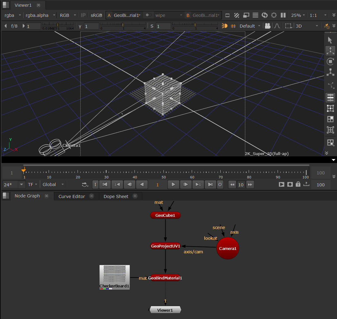
| 1. | In the node graph, select 3D > 3D > Modify > GeoProjectUV to insert a GeoProjectUV node anywhere after the 3D object you want to modify. In this example, we will place the GeoProjectUV node downstream of a GeoCube node. |
| 2. | Attach a Viewer to the GeoProjectUV node. |
| 3. | Connect an Axis or a Camera node to the GeoProjectUV node’s axis/cam input. If you connect an Axis node, project the texture UV coordinates onto the object using the axis transform values (that is, translation, rotation, scale, etc.). If you connect a Camera node, do a similar projection as with the axis but also use the camera lens information, such as the aperture. |
| 4. | In the GeoProjectUV node Properties, adjust the following parameters as needed: |
• From the Projection dropdown menu, select the projection type. Usually, it’s best to select a type that’s close to the object’s surface shape. For example, if your object is a sphere, like a football or a planet, select Spherical.
• From the Plane dropdown menu, select the projection direction: XY, YZ, or ZX to project the texture image along the z, x, or y axis. This dropdown menu is only available if you selected planar as the projection type.
• From the Project On dropdown menu, select Both, Front or Back depending on whether you want to project the texture on the front face of the object, its back face or both. The front face of an object is the one facing the camera and similarly the back face is the one furthest away from the camera.
• Check Cull Behind Projection Source if you want to stop any projections occurring behind the projection plane.
• • Check View Frustum Culling if you want the node to affect only the vertices inside the camera view frustum. Any vertices outside the view frustum are not affected and they still keep their original UV coordinates. Uncheck if you want the node to affect all vertices.
• To mirror the texture UV coordinates in the horizontal direction, check Invert U. To mirror them in the vertical direction, check Invert V.
• To scale (stretch or squash) the texture UV coordinates in the horizontal direction, adjust the U Scale slider. To scale them in the vertical direction, adjust the V Scale slider. The higher the value, the more the texture is stretched.
• To change the name of the attribute that’s used as the vertex’s UV coordinates to find the image pixel, enter a name in the Attribute Name field. If your geometry has more than one set of UV coordinates, you can choose the attribute that suits the projection type. Check the Generate Perspective option to generate an ‘stw’ attribute containing the perspective (w) component of the uv.
• Check the Reference Frame option if you want the projection to only be applied at the frame being referenced, for example if you want to set up projections that stick to moving prims.
| 5. | Now you’ll need to add the image you wish to project and bind this as a material to the object downstream. First, add an image, for example by adding a CheckerBoard or your own image via the Read node. |
| 6. | Connect the image to the mat input of a GeoBindMaterial node to project the image. |

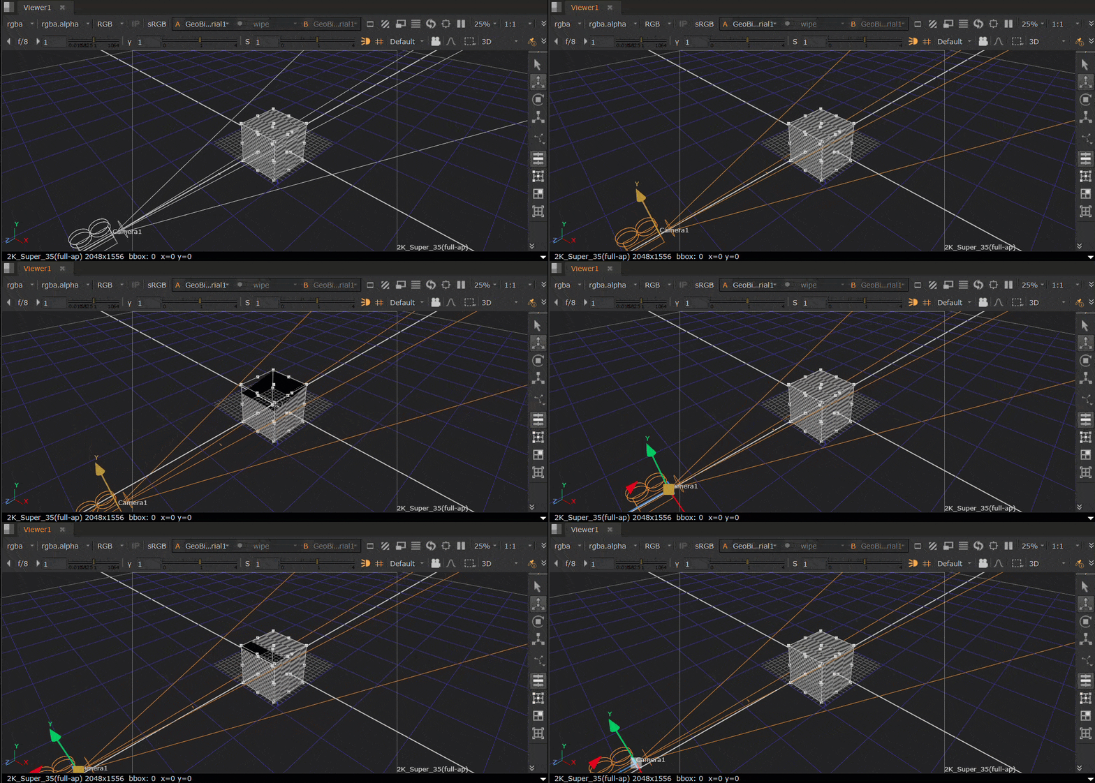
| 7. | You can then transform the Camera to position the material. |

Projecting Textures with the Project3DShader Node
The Project3DShader node projects an input image through a camera onto the 3D object.
