Estimating Lens Distortion Using a Grid
Grid analysis estimates the distortion from a checkerboard or thin line grid. As a general rule, if you have a grid you can use to calculate your lens distortion, you should use grid analysis. Grids are constructed from Features and Links, which are calculated automatically.
|
|
|
|
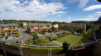
The original distorted shot |
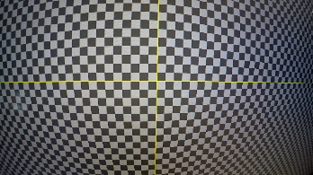
Associated grid shot |
To estimate distortion using a grid:
| 1. | Read in your grid and connect a LensDistortion node, followed by a Viewer. |
| 2. | Set the LensDistortion > Lens Type and Advanced > Projection Model using the dropdowns in the LensDistortion Properties panel. In this example, the lens is Spherical and None (Rectilinear), but there are a number of other presets included. |
| 3. | If you're using a fisheye lens, you need to 'defish' the lens. You can do this by selecting the correct Advanced > Projection Model setting, such as Fisheye Equisolid, entering the Focal Length and Sensor Size. |
Tip: If you don't know the Focal Length, set the Output Mode to Undistort and adjust the Focal Length until the curved lines in the image appear approximately straight. Don't forget to switch back to Mode > STMap before continuing.
| 4. | Set the Model Preset to use for the estimation. Nuke ships with several models for use with CaraVR and 3DEqualizer, as well as a NukeX Classic model. |
The model you choose sets appropriate Advanced > Distortion controls and populates the read only Equation fields showing the math involved in the estimation.
| 5. | The LensDistortion node adds a keyframe on the current frame by default when you click Detect, but you can add more using the |
Adding keyframes can produce a better result for long sequences, but it takes longer to calculate the result.
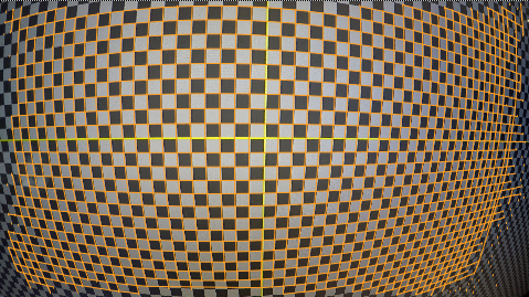
| 6. | On the Analysis tab, click Detect to start the grid calibration. By default, Nuke looks for Features on the grid and then creates Links between those features to create the distortion grid. |
You can enable Preview to view the features that the LensDistortion node is likely to find when you click the Detect button.
Tip: For difficult shots, you can make adjustments between Features and Links detection to improve the results. See Adjusting Grid Detection Parameters for more information.
A grid overlay is displayed when the detection step is complete.
Tip: If the grid does not cover most of the image, try increasing the Number of Features value on the Analysis tab and clicking Detect again.
| 7. | Click Solve to estimate the distortion using the grid. |
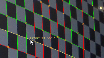
Nuke estimates the distortion and displays a new overlay and overall Solve Error. The default Output Mode is Undistort, so the inverse distortion is applied to the image automatically.
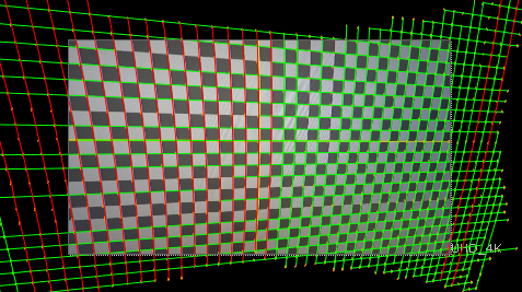
Green lines represent links that fall within the Detection Threshold value and red lines those that fall outside the threshold. You can hover over links to display their solve error.
| 8. | Clicking Solve again can improve the result in some cases. You can also refine the detection and linking before solving again using the controls on the Analysis tab. See Adjusting Grid Detection Parameters for more information. |
Note: You can also output the distortion as an STMap for use in other images. STMaps contain the pre-computed warp data in the motion channel, allowing you apply the warp quickly and easily. See Working with STMaps for more information.
Nuke takes the estimated distortion and uses the result to 'straighten' the feature links.
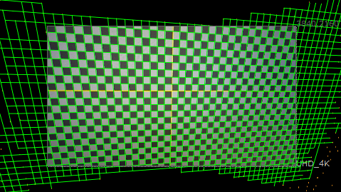
The bounding box is increased beyond the format size to include all the image data from the input image.
| 9. | You can control the bounding box manually using the BBox and Output Format controls on the LensDistortion tab. |
Any areas of the image where there is no data are overscanned, meaning the last pixel available is duplicated to the edge of the format. The area at the top of the image shows overscan.
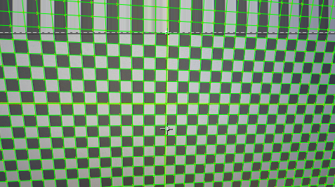
You can also bring more image data into the format bounds using the BBox and Output Format controls.
| 10. | Proceed to Removing Lens Distortion from an Image or Adjusting Grid Detection Parameters to fine tune your grid. |