Generating Disparity Maps
To generate a disparity map, do the following:
| 1. | Launch Nuke and press S on the Node Graph to open the project settings. Go to the Views tab and click the Set up views for stereo button. |
| 2. | From the Toolbar, select Image > Read to load your stereo clip into Nuke. If you don’t have both views in the same file, select Views > JoinViews to combine them, or use a variable in the Read node’s file field to replace the name of the view (use the variable %V to replace an entire view name, such as left or right, and %v to replace an initial letter, such as l or r). For more information, refer to the Nuke User Guide. |
| 3. | Select Ocula > Ocula 4.0 > O_DisparityGenerator to insert an O_DisparityGenerator node after the Read node. |
Note: If you intend to use the Alignment control, O_DisparityGenerator requires an O_Solver node as one of its inputs. Alignment defaults to 0, but increasing it forces the disparity map to match the camera geometry to remove noise on the vertical component of disparity. See Generating Disparity Using Alignment for more information.
| 4. | Open the O_DisparityGenerator controls. O_DisparityGenerator renders using the Local GPU specified, if available, rather than the CPU. The output between the GPU and CPU is identical, but using the GPU can significantly improve processing performance. |
If no suitable GPU or the required NVIDIA CUDA drivers are available, O_DisparityGenerator defaults to the CPU. You can select a different GPU Device, if available, by opening Nuke's Preferences and selecting an alternative card from the GPU Device dropdown.
Note: Selecting a different GPU requires you to restart Nuke before the change takes effect.
| 5. | From the Views to Use menu or buttons, select which views you want to use for the left and right eye when creating the disparity map. |
| 6. | If there are areas in the image that you want to ignore when generating the disparity map, supply a mask either in the Mask input or the alpha of the Source input. In the O_DisparityGenerator controls, set Mask to the component you want to use as the mask. |
Note that masks should exist in both views, and O_DisparityGenerator treats the alpha values of 1 as foreground and blurs to the 0 value using nearby disparity to recreate object boundaries, rather than image data. When you create a mask using Roto or RotoPaint, you can use the feather control to extend the calculation. For example, the disparity map may have a sharper transition at depth edges with a binary mask, but applying feather on the mask can help smooth the resulting image.
| 7. | Attach a Viewer to the O_DisparityGenerator node, and display one of the disparity channels in the Viewer by selecting it from the channels dropdown above the Viewer. |
O_DisparityGenerator calculates the disparity map and stores it in the disparity channels.
|
|
|
|
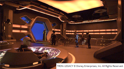
The Source clip. |
A disparity map. |
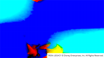
Tip: Reading depth in disparity maps can be tricky in RGB. There are a number of ways to make the depth easier to read, but the simplest is to:
Set the Viewer channels control to disparityL and the R layer within the channel.
Move the pointer around the image to locate the highest positive or negative red value using the Viewer info bar.
Set the gain field to +/-1 divided by the red value. For example, 1/20 for positive values or -1/20 for negative values.
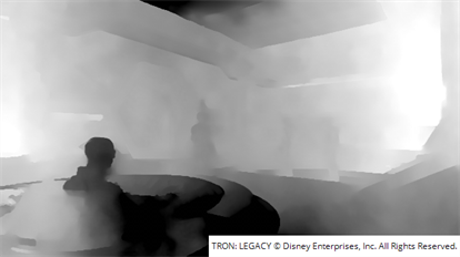
Adjust the gain and gamma controls to reveal edges and areas of contrast. Darker areas of the image are closer to the camera and lighter areas farther away. If you use a positive gain, the light and dark colors are flipped.
|
|
| 8. | If the calculated disparity map does not produce the results you’re after (and you have already checked the quality of the solve as described in Reviewing and Editing the Results), use the O_DisparityGenerator controls to adjust the way the disparity map is calculated. You can either adjust the controls manually or use the Preset dropdown to automatically make adjustments for you: |
• Custom - automatically selected when you adjust the controls manually,
• Normal - the default values for all controls.
• Strong - reduces match Stabilisation between images and concentrates on the Strength of image matching.
• Aggressive - increases the Strength to reconstruct images as close as possible to the source, but reduces Stablilisation in favor of accuracy.
• Smooth - reduces match Strength between images and concentrates on Stabilisation.
• Aligned - enables the Alignment control, which requires an O_Solver upstream. See Solver and Generating Disparity Using Alignment for more information.
• Fast - disables the Stabilisation control, speeding up processing time.
The available controls are described in O_DisparityGenerator Controls.
| 9. | You can also use the Parallax Histogram display in O_DisparityViewer to review the disparity range. For more details, see DisparityViewer. |
Tip: To check the quality of the generated disparity map, you can add a DisparityReviewGizmo from the Ocula > Ocula 4.0 menu. This gizmo allows you to view the disparity in each view using the output and background dropdowns to control what is displayed in the Viewer. See Quality Control Tools for more information.
You can then use a RotoPaint (Draw > RotoPaint) node to edit the generated disparity channels. For example, if a specific region in the image is producing incorrect disparity vectors and you know that those vectors should match the vectors in the surrounding areas, you can use the Clone tool to clone out the problematic area.
You can also use O_MultiSample to fill or replace problematic areas. See MultiSample for more information.
Generating Disparity Using Alignment
Using O_DisparityGenerator in conjunction with O_Solver alignment data allows you to constrain the resulting disparity vectors to match global plate alignment. You might want to do this if your plates don't contain much detail, such as bluescreen images with markers in the background or plates with a lot of featureless areas like sky.
Using the O_Solver alignment data can reduce changes in vertical disparity with depth that are required for Local alignment in O_VerticalAligner and cause a vertical shift in O_NewView, where disparity doesn't pick up the local vertical shift required to match the images.
To generate a disparity map using O_Solver alignment data, do the following:
| 1. | Start Nuke and press S on the Node Graph to open the project settings. Go to the Views tab and click the Set up views for stereo button. |
| 2. | From the Toolbar, select Image > Read to load your stereo clip into Nuke. If you don’t have both views in the same file, select Views > JoinViews to combine them, or use a variable in the Read node’s file field to replace the name of the view (use the variable %V to replace an entire view name, such as left or right, and %v to replace an initial letter, such as l or r). For more information, refer to the Nuke User Guide. |
| 3. | Select Ocula > Ocula 4.0 > O_Solver to insert an O_Solver node after either the stereo clip or the JoinViews node. |
Note: Solve data passed downstream to O_VerticalAligner is updated to match the aligned plates, except when Vertical Skew or Local Alignment is enabled. See VerticalAligner for more information.
O_Solver calculates the geometrical relationship between the two views in the input clip and requires at least one keyframe. For more instructions on how to use O_Solver, see Solver.
| 4. | Select Ocula > Ocula 4.0 > O_DisparityGenerator to insert an O_DisparityGenerator node after the Read node. |
| 5. | Set the Alignment control to a value greater than 1, so that disparity requires solve data upstream. |
| 6. | Continue from step 4 in Generating Disparity Maps to generate disparity vectors, including alignment data from the solve. |