Camera Items
The Camera Item is a virtual lens into the 3D world inside Modo. Everything rendered is seen from the camera's point of view, and the camera's settings determine how the 3D world is captured. The camera works in conjunction with the Render Item, generating a virtual snapshot in the Render Display.
The image that is displayed depends on your render output. This acts as a virtual developer by determining what actually gets rendered when any render command is invoked.
Tip: You can also invoke the renderer by pressing F9.
The Camera Item contains the properties that define the projection, frame aspect ratio, depth-of-field, and other attributes. However, the actual frame resolution is set within the Render Item under the Frame properties.
Adding a Camera Item
Each new Modo scene has a single camera item by default. A new camera can be added to the scene by the following methods:
• Select Item > Create Camera from the menu.
OR
• In the Item List, click Add Item and select Locators > Camera.
Choosing a Render Camera
Additional cameras are helpful in providing alternate views of a scene, easing navigation, or for providing close-up views of a particular area, especially in situations where the hero (principle) camera is animated and locked, avoiding accidental changes. Only a single camera may be rendered at a time, the particular camera used is specified in the Render Item: Frame sub-tab under the Render Camera option. Additionally, alternate cameras may be selected within the Render Preview viewport using the select camera option available, without affecting the Render Camera used for final rendering.
To quickly identify which camera is used as the render camera, in the Items lists, bold text and a render icon is displayed. In the image below, an additional camera was added to our scene to demonstrate the difference in the display of camera items. To set a camera in your Items list to a render camera, right-click on the camera item and select Set as Render Camera.
![]()
Working with the Camera
Camera attributes, such as Position and Rotation, can be modified in the Properties panel whenever the Camera Item is selected in either the Item List or the Shader Tree. By default, the camera icon is only visible in the Animate and Render 3D Viewports, but by changing the visibility in the viewport options, they can be made viewable in any viewport.
Hover the mouse pointer over the 3D viewport you wish to modify, and press O on the keyboard to open the 3D viewport Properties panel.

Camera Items can be modified interactively in the 3D viewport while in Items mode (Camera Items have no editable components). Use the standard transform tools to move (W) and rotate (E) the camera. When making fine adjustments, you may find it easier to see how the camera is viewing the scene. This can be done by changing the viewport view button in the upper left to Camera. When set as such, black bars may be drawn over the viewport if the aspect ratio of the Frame Size is different from the viewport's aspect ratio. The area inside the bars represents the area of the scene that renders when a render command is invoked.
To position the camera while in this view mode, various keyboard/mouse options are available.
|
Keyboard/Mouse Options |
Camera Actions |
|---|---|
|
Shift+Alt+Left-click and drag |
Move camera item |
Shift+Alt+RMB Drag |
Move Up/Down direction only |
|
Alt+Left-click and drag |
Rotate around Target Distance |
|
Alt+Right-click and drag |
Rotate around Camera center |
|
Ctrl+Middle-click and drag |
Rotate around the Z axis |
|
Ctrl+Alt+Left-click and drag |
Move Forward/Backward only |
|
Ctrl+Alt+Right-click and drag |
Adjust Focal Length |
|
Roll Mouse Wheel |
Move Forward/Backward only |
When tool handles are set to Advanced (within the Preferences or Tool Pipe), additional handles become visible, allowing you to interactively adjust camera setting in the viewport. The handles are:
• Adjust Focal Length/Field of View
• Adjust F-Stop for Depth of Field
• Adjust Convergence Distance
• Adjust Focus Distance
• Parallax Offset Difference value (distance between items for left and right eye in final rendered frame) expressed as percentage of frame width
You can drag the handle around the scene to get an idea how far apart elements appear on the screen when rendered as a stereo image.
Generally speaking, for comfortable viewing you should keep the sum of the values for the closest elements in frame to the farthest elements around 5% and under. Adjustments can be made to Interoccular Distance and the Convergence Distance options to help in obtaining this result.
Tip: You may find it more intuitive to adjust the camera when the Action Center is set to Local, keeping the transform handles aligned to the Camera Item itself.
On occasion, you may wish to modify the size of the camera icon within the 3D viewport. This can be accomplished with the Size setting in the Display viewport, which offers additional settings for modifying the camera's icon representation, including the ability to label the item, enable the Safe Area display, and toggle the display of the Stereo Volume. You can also adjust the camera's Scale option in the Properties panel.
Note: Changing the size of the camera icon in no way affects the rendering outcome or the overall scale of the scene.
Markup
The Markup tool allows you to draw directly onto selected camera views so you can add annotations, notes, and comments for your animations or stills. Assign Markup to the current camera item by selecting the camera and clicking Markup in the Images properties. You must make the current camera active in the viewport before you can create the Markup image. Once assigned, you can use a selection of Markup tools and controls to draw on your viewport. See Markup for more information.
Tip: The Markup tool can be used in conjunction with animated scenes by moving to a frame and drawing. The Markup images for each frame are displayed when scrubbing through frames or during normal animation playback.
Foreground and Background Images
Each camera can be assigned a foreground and background image to supplement a scene. The foreground image is only visible in the render view so as not to obscure any geometry, whereas the background image is always visible from the camera. To preserve the background image aspect ratio, you can override the render resolution with the background image resolution. For detailed instructions, see Camera Images.
Camera Matching
The camera background image acts as a backdrop to geometry when rendering a scene. To make the geometry look like it's in the backdrop you can use Camera Matching. Camera Matching adjusts the camera position so that the perspective in the camera background image matches the perspective of the Modo world. This allows you to place geometry as if it were part of the background image. For full instructions, see Camera Matching.
Camera Image Planes
In addition to foreground and background images, Modo cameras support multiple image planes. Using image planes, you can position a material so that it faces the camera at any distance from the camera viewpoint. This lets you layer images, allowing you to insert geometry between the layers. For full instructions, see Camera Images.
Camera View Properties
The first property is the camera's Name, which can be edited to help identify the camera in the Items list.
Other Camera View properties:
• Resolution Override Properties
Transform Properties
![]()
These properties define the camera position and orientation.
|
Transform |
||||||||||||
|
Position |
An item transform that allows you to numerically position the Camera Item in XYZ space. By default, Position transforms originate from the item's center position. |
|||||||||||
|
Rotation |
An item transform that allows you to numerically set the rotation of the Camera Item. By default, Rotation transforms originate from the item's center position. |
|||||||||||
|
Order |
Allows you to set the order in which rotations are applied to the Camera Item. Changing the order that rotations are applied can sometimes help to reduce, or eliminate gimbal lock. |
|||||||||||
|
Scale |
An item transform that determines the size of the icon in the 3D viewport. Scale otherwise has no effect on the final rendered image. |
|||||||||||
|
Reset |
Resets the selected transform values to (0,0,0), returning the items to their default state. |
|||||||||||
|
Zero |
Returns the Camera Item's Center position to the world space center (0,0,0), without changing the position of the Camera Item itself. |
|||||||||||
|
Add |
Transform Items are the channel groups associated to an item that store its transform values, controlling its position, rotation, and/or scale. By default, new items do not have any transform items associated with them (even though they are visible here within the Properties panel). This is useful as an optimization as only the necessary transforms are added on an as-needed basis, reducing scene overhead. There are several ways to add Transform Items. One is by simply transforming the target item with one of the various transform tools (or by editing the values input fields). This action causes the particular transform item to be added automatically to the Channels viewport list. The Add function here can also be used to add the selected set of transforms to the Channels list while keeping the default 0,0,0 values (a necessary step for Referencing; in order to override channels, they must first exist). |
|||||||||||
|
Set Target |
This option allows you to target specific items in a scene, automating the rotation of an item, so that it continuously points toward the targeted item. To use Set Target:
Remember though, that the camera looks directly at the item's center position, regardless of the location of geometry within the target layer. Once activated, additional options appear: • Remove Target - Removes the target link between the two items. • Enable - Toggling this option off temporarily disables the targeting function while retaining the link between the items. • Set Focus Distance - This option sets the focal distance for DOF when targeting camera items to other item. • Roll - Provides the ability to offset the item's rotation angle away from the target. • Time Offset - Specify the time in seconds for the camera following to be ahead or behind the item movement. The camera movement is still dictated by the item movement, but when the Time Offset is a positive value, the camera tracks ahead by the specified number of seconds, effectively predicting the item's movement. If the Time Offset is a negative value, the camera will lag behind by the specified number of seconds. |
|||||||||||
|
Target Distance |
This value defines the point around which the camera orbits. When you start a fresh project, the camera is back 4M on Z and the Target Distance is 4M. That is why it orbits around 0. This value is reset automatically when you zoom in the 3D viewport. Modo fires a ray out from the camera and automatically sets the target distance based on the first surface the ray intersects. |
|||||||||||
|
Sync to View |
This option changes the position and orientation of the currently selected Camera Item to match the currently selected 3D viewport as closely as possible. There are some caveats in that the camera's view scale depends on the focal length and image resolution (for aspect) and therefore cannot be matched precisely. |
|||||||||||
Projection Properties
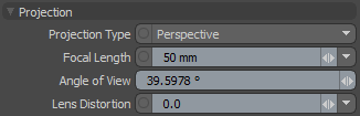
These properties define how the world is seen through the camera based on the projection and lens properties.
|
Projection |
|||||||||||
|
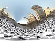
Projection Type |
Modo can render traditional perspective cameras as well as orthographic cameras and spherical cameras. This control allows you to choose the desired camera type: • Perspective cameras show perspective distortion where the scale of an element appears to diminish in the distance. This traditional perspective view is what most artists would expect when rendering; similar to what a real world camera might capture. Perspective cameras are found most often in visual FX, product and architectural visualization, and anywhere artists are trying to mimic reality. • Orthographic cameras do not exhibit any perspective distortion as all rays are fired from the camera in parallel lines. Orthographic rendering is very useful in news/info graphics and architectural plan rendering. • Spherical cameras capture the entire 360 degree view of a scene. Spherical cameras are useful in capturing images that can be later applied as image based lighting and reflection maps, among other things. • Cylindrical projection captures the entire 360 view from the perspective of a tube, removing the polar areas of the projection. • Cylindrical and Spherical VR projection types are intended for applications like virtual reality. They differ from the previous types in that they are not flipped, but centered on the camera view direction. |
||||||||||
|
|||||||||||
|
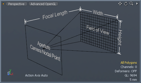
Focal Length |
This setting controls the amount of zoom, just as it would with a real world camera. The actual definition of Focal Length is the distance between the lens and the point where the rays converge after having been refracted by the lens. Wide angle lenses (those with short focal lengths) capture more of a given scene than their telephoto counterpart. Lower focal lengths exhibit more perspective distortion, conversely, longer focal lengths minimize the effect of perspective. To zoom out you should decrease the focal length and to zoom in you increase the value. This control is set in real world metric units to match physical cameras. Focal Length can be adjusted on the Camera Properties panel or interactively in the 3D viewport. If you are looking through the Camera (and 3D viewport set to Camera) you can use Ctrl+Alt+right-click and drag to adjust the Focal Length interactively (Ctrl+Alt+left-click and drag moves the camera itself forwards and backwards). |
||||||||||
|
Angle of View |
In some instances, it may be easier to specify an angle of view instead of a Focal Length. This setting allows you to specify the Angle of View as a number of degrees horizontally, and once set, the Focal Length is updated to reflect the new value. |
||||||||||
|
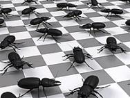
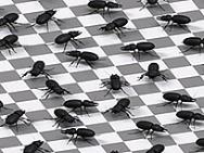
Lens Distortion |
In a real world camera, light rays are bent through a spherical lens element resulting in a slightly distorted image. 3D rendered images don't pass through a lens and likewise don't exhibit the distortions we're accustomed to in photography. The Lens Distortion setting can be used to introduce these familiar distortions in a realistic way. Positive values create an increasing Barrel distortion, and negative values create increasing Pincushion distortion effects. |
||||||||||
|
|
|
||||||||||
|
Standard CG Wide Angle View |
Same view w/ Lens Distortion applied |
||||||||||
Resolution Override Properties
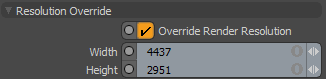
These properties allow you to set a resolution to override the Render Item resolution.
|
Resolution Override |
|||
|
Override Render Resolution |
Check this to specify a resolution to use for rendering through this camera. |
||
|
Width |
The width in pixels. |
||
|
Height |
The height in pixels. |
||
Images Properties
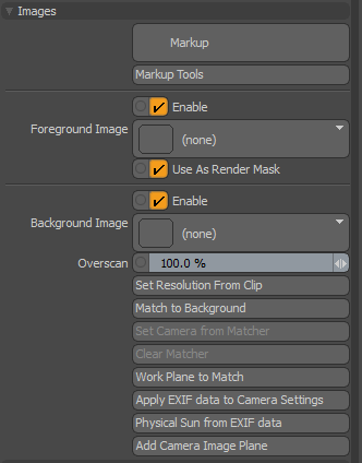
The camera item Images properties panel.
Markup
The Markup tool allows you to draw directly onto selected camera views so you can add annotations, notes, and comments for your animations or stills. See Markup for more information.
|
Markup |
Pressing the Markup button assigns a Markup drawing to the currently selected camera. Note: You must have the selected camera active in the viewport for the Markup tool to become available. |
|
Markup Tools |
Opens the Markup tool popover. See Markup. |
Foreground Image
These properties allow you to add a foreground image, which may be also used as to mask the render output. For more information, see Foreground and Background Images.
|
Foreground Image |
|||
| Enable |
Enables the Camera image to use the Foreground Image. When disabled, the Foreground Image is not displayed in your rendering but it is not removed. This option is Enabled by default. |
||
|
Foreground Image |
Add a foreground image to the near viewing plane. This is only visible when rendered. |
||
|
Use As Render Mask |
Check this to use the foreground image as a mask for the render output. White areas in the image are fully transparent, and black areas are fully opaque and omitted from the render. The darker the shade, the more opaque the mask. |
||
Background Image
These properties allow you to work with background images and image planes. For more information, see Camera Images.
|
Background Image |
|||
| Enable |
Toggles to enable or disable Camera images that are used for Background Image without removing it. This option is Enabled by default. |
||
|
Background Image |
Add a background image to the far viewing plane. This can be used for Camera Matching to match the perspective of the camera to the background image. |
||
|
Overscan |
Scale the background image without changing the aspect ratio. |
||
|
Set Resolution from Clip |
Set the render resolution to match a selected clip. The Background Image is used if one has been added. |
||
|
Match to Background |
Click this to start the Camera Matcher. For full instructions see Camera Matching. |
||
|
Set Camera from Matcher |
Match the camera perspective to the image perspective according to the perspective lines that have been drawn when using the Camera Matcher. In short, match the camera. |
||
|
Clear Matcher |
Reset the Camera Matcher. |
||
|
Workplane to Match |
Match the Work Plane to the axes and position as drawn in the Camera Matcher. |
||
|
Apply EXIF data to Camera Settings |
Use EXIF data to define the camera's Focal Length. See EXIF Data. |
||
|
Physical Sun from EXIF data |
Use EXIF data to create a Physical Sun directional light. See EXIF Data. |
||
|
Add Camera Image Plane |
Add a quad polygon on an image plane in the camera frustum. This opens the Camera Plane properties tab. Adjust the Depth to position the plane at a suitable distance from the camera viewpoint. The quad is scaled automatically to fill the camera frame. See Image Planes. |
||
Film Back Properties
In the real world, every camera has certain attributes of fixed physical size. In the analog days, this was based on the film size (such as 35 mm, 70 mm, and so on). With digital cameras, it is the sensor size (such as 1/3, 1/2, APS, and so on). The size of this fixed capture area works in conjunction with the focal length to control the field of view that is captured. Modo offers the ability to modify the virtual capture area to any conceivable size.
For example, should you wish to compose 3D rendered elements together with images from a camera, for the most convincing results, matching the real-life sizes and aspect ratios of the original camera is highly recommended. Many popular preset sizes are provided for convenience, but you can also define custom values with the Width and Height settings. The Film Fit setting allow you to control Modo's behavior when the frame size specified in the Render Item, is a different aspect ratio than the film back settings.
|
Film Back |
|||||||||
|
Film Back Preset |
This control allows you to choose from a number of available preset real world cameras. Choosing a preset automatically sets the Film Width and Height, and the corresponding Frame Size (in the Render Items > Frame Tab). You can also save your own presets by selecting (new preset) from the bottom of the list. When selecting this option, a dialog displays asking you to name your preset. Your new preset is saved in Modo's config file and is available immediately for selection. |
||||||||
|
|
|||||||||
|
Film Width/Height |
Film Width and Film Height correspond to the exposed region of the film negative in a real camera set in real world measurements. In some applications, this is known as the Film Gate. One way to visualize this is to imagine the camera frustum as a pyramid whose base dimensions are the Film Width and Height and terminating at the apex. The distance from the base to the apex is the Focal Length (the apex being the position of Modo's virtual aperture and the position where the camera rotates, which incidentally, is also the nodal point). The base of the pyramid can be shifted around within its plane (shearing the pyramid) by using the Film Offset controls. |
||||||||
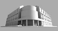
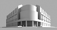
|
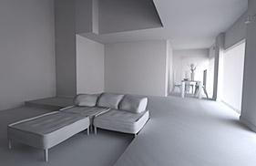
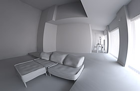
This function allows you to offset the position of the Film Back without changing the position of the Camera Item itself, providing unique perspective views not otherwise possible. The function is especially useful when rendering architectural type images that prefer two point perspective as opposed to three. By rotating the camera on the X axis to 0° (eliminating the vertical perspective), the offset can be adjusted to modify the camera's view (framing the subject properly) while retaining the perspective of the camera's original position. The three images below illustrate the differences between film offset and simply moving the camera. A.) The camera standard perspective view with the subject centered in the frame. B.) Rotates the camera X axis to 0° and uses a Film Offset to frame the subject eliminating the vertical perspective. C.) Is the default perspective camera again with no offset, but the camera was rotated to 0° on the X axis again and the camera's position was modified upward to frame the subject producing a dramatically different perspective than that offered by B.
|
|||||||||
|
Film Roll |
Allows for 2D camera rotation. The results are displayed in the 3D Viewport when the animation is played. The rotation is relative to the Film Offset X/Y values.
|
||||||||
|
Film Fit |
Film Fit only matters when the Camera Item's film gate (defined by the Film Width and Height above) has a different aspect ratio than the Render Item's resolution gate (defined by the actual frame's Width, Height, and Pixel Aspect Ratio). In that case, the two possibilities are that the horizontal borders coincide, or the vertical borders coincide. The Fill and Overscan options automatically select whether to match the horizontal or vertical borders in order to make the resolution gate fit within the film gate or vice versa. You can think of the film gate (Film Width and Height) as the size of the film in the camera in real world units, with the film being analog (not divided into pixels). Then you take the exposed film frame and lay it on a digital scanner (the resolution gate), which is divided into pixels, and which might have a different shape (wider or taller). It's the resolution gate that gets saved to the output image file. |
||||||||
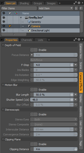
Camera Effects Properties
|
|
|
|
|
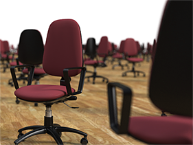
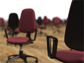
Distant Chair in Focus |
|
Near Chair in Focus |
|
Option |
Description |
|||||||||
|---|---|---|---|---|---|---|---|---|---|---|
|
Depth of Field |
||||||||||
|
Depth of Field (DOF), as it relates to photography, is the area of acceptable focus in an image; any area outside gets increasingly blurry as it recedes from the focal plane. The softening of edges as they recede from the plane is highly dependent on the F-Stop setting. Smaller values represent larger apertures producing softer blurs, conversely, higher values represent smaller apertures producing less blurriness. |
||||||||||
|
Enable |
This option toggles the Depth of Field effect on and off when rendering. |
|||||||||
|
Focal Distance |
When rendering with Depth of Field enabled, this value sets the distance out from the camera center at which the image is perfectly in focus. To quickly set the focus distance for the camera, you can use the Autofocus button or press Ctrl+A with the mouse over the Camera viewport. You can also set this value interactively with the Item Transform tool (Y) when the Camera item is selected. |
|||||||||
|
Autofocus |
This command sets the Focal Distance to whatever geometry is at the direct center of the current camera view. Setting the Focal Distance is only useful when rendering with Depth of Field enabled. You can also use the keyboard shortcut Ctrl+F when the mouse is over any Render Preview window. |
|||||||||
|
F-Stop |
This control on the Modo camera is only effective when Depth of Field is enabled. In this case, lowering the F-Stop decreases the depth of field (apparent area of focus) just as it would in real-world cameras. Note: F-Stop does not affect exposure of light since the Modo camera captures real world radiance values as they are striking the virtual CCD. This provides linear light values to the final image which provides an opportunity for post processing the exposure for maximum flexibility. |
|||||||||
|
Iris Blades |
This controls the way the blurriness looks in images with shallow depth of field, generally referred to as Bokeh. Bright areas, when out of focus tend to take on the shape of the camera's iris, so a smaller number of blades make more obvious geometric patterns in the bokeh shapes, while larger values look more circular. A setting of 0 makes a perfectly circular shape. |
|||||||||
|
||||||||||
|
Iris Rotation |
This option changes the rotation angle of the virtual iris when rendering shallow depth of field in images, which in turn rotates the bokeh shapes in the final rendered output. |
|||||||||
|
Edge Weighting |
When Modo calculates Depth of Field, rays are fired in a pattern that simulates the iris blades producing the bokeh effect shapes. The edge weighting option concentrates those rays toward the center or edges of the iris, depending on the value. A value of 0% concentrates all the values at the center of the iris, while a setting of 100% concentrates the rays toward the outer edge. A value of 50% evenly distributes the rays. As light tends to be stronger in the outer edge of the iris in the real world, setting around 60% to 70% tend to produce the most realistic results. |
|||||||||
|
||||||||||
|
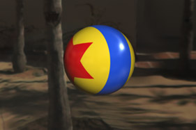
Motion Blur |
||||||||||
|
Real cameras don't freeze time, but capture brief moments, causing moving objects to blur in the frame. This natural motion blur that our eyes are accustomed to can be simulated in Modo. Once Motion Blur is enabled, Modo takes time samples forward and backward from the rendered frame blending them together to create the blur effect. Depending on the strength of the effect or the speed of motion in your frame, you may find it necessary to increase the number of anti-aliasing samples. Adjustments to Blur Length (like adjusting the exposure time for more or less blur) and Blur Offset can be found in the Camera Item's properties.
|
||||||||||
|
Enable |
This option toggles the Motion Blur effect on and off when rendering. |
|||||||||
|
Blur Length |
This control affects the length of the motion blur effect when rendering animations. The default value of 50% is similar to a real-world camera set with a 180 degree shutter. In Modo, the 50% value results in the shutter being open for half of the exposure time of that frame. The blur effect is calculated by taking time samples both forwards and backwards from the current frame time and blending them together for the final blurred result. As such, it may be necessary to increase the level of anti-aliasing to produce a smooth result. |
|||||||||
|
Shutter Speed (1/s) |
Sets the shutter speed of the camera. The slower you set the shutter speed, the more pronounced the motion blur effect gets. You can enter a value manually or use one of the value presets by clicking on the small arrow on the right of the field. Here you can also save new presets by clicking (new) or remove an existing preset by clicking (delete). |
|||||||||
|
Blur Offset |
This lets you control the center position in time where Modo samples its motion blur from. A setting of zero centers the motion blur on the current rendered frame, while a setting of -100% moves the position backwards one entire frame and a setting of 100% moves the position forward one entire frame. Tip: The Antialiasing setting's effect is most apparent on geometric edges. A setting of 8 is generally acceptable and is a good trade off between quality and speed, though in reproducing effects such as Depth of Field or Motion Blur you may need to increase this value, possibly all the way up to 1024 to produce a pleasing result. If you find your shaded edges, such as cast shadows, refractions, reflections, procedural and image based textures are aliased (not smooth), then reducing the shading rate value or lowering the refinement threshold can help to increase shaded edge quality. If you are finding specific areas of an image to be noisy, that cannot be solved by Antialiasing and Refinement, such as soft reflections, blurry refractions, soft shadow edges, subsurface scattering, it may simply be a case where raising the number of samples specific to the effect eliminates the noise. These setting can be found in the associated Properties panels. Always keep in mind though, as more calculations are taken into account, the longer an image takes to render. |
|||||||||
|
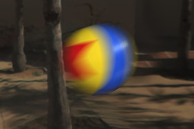
Stereoscopic |
||||||||||
|
We see with two eyes, each slightly offset from the other, providing our brains with enough information to create a sense of depth to the world around us. Modo scenes are likewise 3D with depth, but the monitors we view scenes with are two-dimensional, as are the renders Modo creates. Activating the stereoscopic function in Modo brings back that missing depth information by rendering two offset images, that when viewed in tandem, reveal the depth present in your original scene. The Stereoscopic function, when enabled, renders two separate frames, one appended L for left and R for right, noting which eye the frame was rendered for. Note: When enabled, the Stereoscopic function is rendering two completely separate frames, so increased render times are to be expected. If applicable, only a single Irradiance Cache is calculated for stereoscopic renders.
|
||||||||||
|
Stereoscopic Enable Toggle |
This setting is the global toggle to enable or disable the Stereoscopic function when rendering. When enabled, Modo renders two frames slightly offset from each other (like our eyes). The resulting images can then be combined in a variety of ways that, when viewed appropriately, reveal the depth present in your original scene. |
|||||||||
|
Stereo Eyes |
When Stereoscopic rendering in enabled, you can use this option to choose which eye is rendered. Choose to render only the Left eye, only the Right eye, or both simultaneously. When rendering both, you can additionally choose a Stereo Composite option to determine how Modo combines the resulting stereo images for final output. |
|||||||||
|
Stereo Composite |
Modo offers a variety of options for composing stereo images into a single image for viewing. Which option you choose is largely based on how the resulting image is viewed: • Anaglyph Red-Cyan - This method replaces the red channel or the right image with the red channel from the left image. • Anaglyph Grayscale - This method makes both frames into grayscale (luminance) images, then puts the left one in the Red output channel and the right one in the Green and Blue channels. • Anaglyph Red-Cyan Half Color - This method basically converts the left image to grayscale and puts it into the Red channel, and uses the right frame's Green and Blue channels for the output Green and Blue channels. This technique reduces 'retinal rivalry', which is a disturbing phenomenon caused by differing brightness of what should be the same objects seen by either eye. • Anaglyph Red-Cyan Optimized - This method further combats retinal rivalry by discarding the red channel from both images, keeping the right frame's cyan component, and mixing the left frame's Green and Blue channels at 70%/30% ratio to use in the output red channel. • Anaglyph Red-Blue Least Squares - This algorithm was invented by Eric Dubois. He used the optical properties of standard red and blue filters used for anaglyph glasses and derived magic numbers for blending stereo pairs into color anaglyphs by minimizing the error using a "least squares" method. • Side-by-Side - Half-width frames are rendered and composed side by side into full width regular frames, with Left on Left and Right on Right. • Side-by-Side Full Width - Full sized frames are rendered separately and composed side by side in double width frames, with Left on Left and Right on Right. • Side-by-Side Cross Eyed - Half-width frames are rendered and composed side by side into full width regular frames, with Left on Right and Right on Left. • Side-by-Side Cross Eyed Full Width - Full sized frames are rendered separately and composed side by side in double width frames, with Left on Right and Right on Left. |
|||||||||
|
Interocular Distance |
The Interocular Distance technically means the distance between the center point of a person's two pupils, but here it is the measured offset between the two rendered images in Modo. The default setting of 65 mm is the average distance between the eyes of an adult. For scenes modeled to real world values, this is an appropriate setting that produces good results. Scenes of varying scale or exceptionally close/far objects may require this distance to change. |
|||||||||
|
Convergence Distance |
The convergence distance is the point within 3D space where the two offset images converge. In front of this point, objects appear to come forward, and behind this point, object appear to recede. It is easily understood by imagining it as the focal point of your scene, much like with DOF. Where the focal distance is the position in space where all objects are in focus, objects in front or behind this position gradually blur, the Convergence Distance is the point in the scene you wish to direct your viewers eyes, as it is the most comfortable to view. This is exactly how your eyes work as well. If you were sitting in a restaurant and your eyes were focused on your glass of water on the table, this would effectively be the convergence point of your two eyes, your dinner plate would be in front of the glass coming forward, and your guest would be further away on the other side of the table. |
|||||||||
|
Clipping Plane |
||||||||||
|
Clipping refers to removing part of a scene from a rendered image while leaving the actual scene geometry intact. You can define a distance where all (or selected) surfaces are clipped, by enabling the Clipping Plane option and then defining a Clipping Distance. You can disable clipping on a per-material basis by disabling the Enable Surface Clipping option in the Material item. Tip: A similar effect can be obtained through the use of Render Booleans that are not camera view dependent. |
||||||||||
|
Enable |
When enabled, any scene items within the bounds of the camera position and the clipping plane are clipped from the scene, removing them from the rendered image while retaining the actual scene geometry. |
|||||||||
|
Clipping Distance |
Defines the distance away from the camera where items are clipped. |
|||||||||
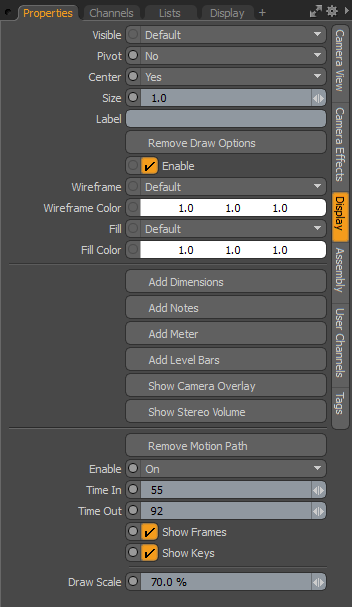
Camera Display Properties
The camera display options can be accessed from the Display tab in the camera's Properties viewport. These options determine how the camera is drawn in the 3D viewport.
|
Camera: Display |
|||
|
Visible |
Sets visibility for the item itself in the 3D viewport. Options are: • Default - respects viewport settings. • Yes - sets the item as always visible. • No - disables visibility entirely. • No (Hide Children) - disables visibility of all related child items. |
||
|
Pivot |
Sets visibility for the 3D item center. Options are: • Default - respect viewport settings. • Yes set the center as always visible. • No - disable center visibility entirely. |
||
|
Center |
Sets visibility for the 3D item center. Options are: • Default - respect viewport settings. • Yes - set the center as always visible. • No - disable center visibility entirely. |
||
|
Size |
A multiplier that adjusts the display size of the locator. |
||
|
Label |
Displays next to the locator in the viewport for easy identification. It adds two additional properties to control the display of the label in the viewport: Show Label and Label Offset. |
||
|
Show Label |
Temporarily enables/disables the display of the label in the viewport without losing settings. This option is only available when a label is specified. |
||
|
Label Offset X, Y |
Specifies the X and Y distance away from the locator where the label appears. This option is only available when a label is specified. |
||
|
Add/Remove Draw Options |
The Draw Options control the look of the locator in 3D Viewports, they are mostly used to define a custom wireframe color for the camera item. |
||
|
Enable |
|
||
|
Wireframe |
Determines the camera wireframe draw style. Options are: • Default - The standard white wireframe. • User - The color can be customized using the Wireframe Color setting. • Background Light - A color to retain camera wireframe visibility against a light background. • Background Dark - A color to retain camera wireframe visibility against a dark background. |
||
|
Wireframe Color |
Determines the camera wireframe color when the Wireframe mode is set to User. |
||
|
Fill |
If the viewport style is set to Solid (see 3D Viewport Styles), this setting determines the fill color of 3D items. • Default - The standard gray fill. • User - The color can be customized using the Fill Color setting. • Background Light - A color to retain item visibility against a light background. • Background Dark - A color to retain item visibility against a dark background. |
||
|
Fill Color |
Determines the item fill color when the Fill mode is set to User and the viewport style is set to Solid. |
||
|
Add/Remove Dimensions |
When enabled, dimension values for the overall bounding box size appear in the viewport around the selected mesh item. An additional Dimensions sub-tab shows in the Properties viewport, allowing further display customizations. |
||
|
Add/Remove Notes |
When enabled, you can define multiple lines of text (up to nine) that show up when the item is selected. An additional Multi-Line Notes sub-tab shows in the Properties viewport, allowing further customization. |
||
|
Add/Remove Meter |
When enabled, displays an on-screen analog-style meter graph (this looks like a speedometer) that can be rigged to show individual values in the 3D viewport. An additional Dial Meter sub-tab shows in the Properties viewport, allowing further customization. |
||
|
Add/Remove Level Bars |
When enabled, displays an on-screen equalizer-type graph for visualizing multiple on-screen values. An additional Equalizer Bars sub-tab shows in the Properties viewport, allowing further customization. |
||
|
Show/Hide Camera Overlay |
When enabled, displays the camera overlay graphics. An addition Camera Overlay sub-tab shows in the Properties viewport. For a full description of camera overlays see Camera Overlay Features. |
||
|
Enables the display of the Stereo Volume guides in the 3D viewport to give you an understanding of the amount of parallax in a given stereo scene. When enabled, a series of options to control the size and opacity of the guides can be found in the Camera item's properties panel only when the Show Camera Overlay option is enabled. |
|||
|
Add/Remove Motion Path |
Displays the animation motion path (if any) for the camera. Clicking Add Motion Path reveals further customization parameters. |
||
|
Enable |
Determines if the path draws. Options are: • Off - don't draw the motion path. • On - draw the motion path irrespective of selection status. • Selected - draw the motion path if selected. |
||
|
Time In |
The number of frames before the current time in the timeline that are displayed by the curve. |
||
|
Time Out |
The number of frames after the current time in the timeline that are displayed by the curve. |
||
|
Show Frames |
Toggles the dots along the curve that mark each frame along the motion path. The dots can be useful to see how the element moves in time, but can also cause clutter for some types of motion and so can be disabled. |
||
|
Show Keys |
Toggles the white dots that mark the keyframes along the motion path. |
||
|
Draw Scale |
This extrudes a ribbon shape outward from the motion path that represents the orientation angle of the animated element. The larger the scale value, the wider the ribbon representation in the viewport. |
||
Camera Overlay Features
Modo's camera view can be augmented with a number of overlays to help you compose a scene. You need to enable these options by clicking Show Camera Overlay in the Display tab of the camera item Properties. This adds the Camera Overlay tab to the Properties panel.
Tip: The Camera Overlay guides only appear when a viewport is set to the Camera view type. Also, the camera must be set to Visible within the viewport. Ensure Show Camera is enabled in the Visibility options and the camera is visible in the Items (Scenes) List.
Camera Overlay
The Camera Overlay section allows you to toggle and resize the safe area guides. It also contains controls for adjusting the appearance of any overlays.
Safe areas help you take overscan into account, when composing the camera view. Overscan occurs in broadcasting, and refers to the situation in which the image is blown-up larger than the visible screen size. This means that not all of the image is seen on screen as the image is magnified and cropped.
To manage overscan, broadcasters work within safe areas. A safe area is a region of the image that should not be affected by overscan. Two universal safe areas have been adopted:
• Title Safe - An area where text is guaranteed not to be cropped. Text such as titles or subtitles should be placed in this area.
• Action Safe - A larger area that marks the edge of the picture that is likely to be seen on screen. Unlike text, it is acceptable for the action to reach the edges of the Action Safe area.
Note: It is not advisable to have text up against the edge of the screen, and so the Title Safe area is always smaller than the Action Safe area.
The image below shows typical Title Safe and Action Safe area boundaries as shown in Modo.
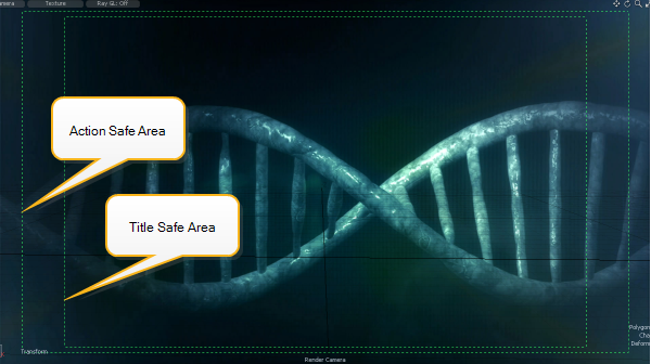
Note: The safe areas used in the image above correspond to those used by the BBC for 16:9 images. The title safe area is 80% horizontal by 90% vertical, and the action safe area is 93% horizontal by 93% vertical.
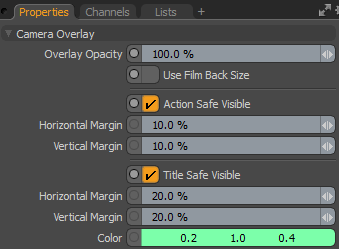
Camera Overlay Properties
|
Camera Overlay |
|
|
Overlay Opacity |
Adjusts the transparency of the overlay. This applies to the safe areas, the Composition Guides, and the Lines. |
|
Use Film Back Size |
Check this to calculate overlay size based on the Film Back Properties size, rather than the render image size. Note: Leave this unchecked unless you have a specific reason to do so. Older versions of Modo (pre-902) used the film back size to generate overlays, but this was found to be problematic. The option has been left in to maintain compatibility with previous versions. That said, it may be useful if you wish to use the film back size as a guide when rendering the scene to different image resolutions. |
|
Action Safe Visible |
This option toggles the visibility of the Action Safe area boundary. The Action Safe area is the region in which the important action of a scene should be clearly visible. The bounds of this area are likely to match the edges of the viewing screen. |
|
Horizontal Margin |
This determines the Action Safe boundary distance away from the left and right edges of the camera viewport. The value applies to each side of the boundary. To show a horizontal Action Safe area of 93%, you would set the Horizontal Margin to 3.5% (7% divided by 2). |
|
Vertical Margin |
This determines the Action Safe boundary distance away from the top and bottom edges of the camera viewport. The value applies to each side of the boundary. To show a vertical Action Safe area of 93%, you would set the Vertical Margin to 3.5% (7% divided by 2). |
|
Title Safe Visible |
This option toggles the visibility of the Title Safe area boundary. The Title Safe area is the region in which on-screen text and graphics are guaranteed to be visible and clearly legible. |
|
Horizontal Margin |
This determines the Title Safe boundary distance away from the left and right edges of the camera viewport. The value applies to each side of the boundary. To show a horizontal Title Safe area of 80%, set the Horizontal Margin to 10% (20% divided by 2). |
|
Vertical Margin |
This determines the Title Safe boundary distance away from the top and bottom edges of the camera viewport. The value applies to each side of the boundary. To show a vertical Title Safe area of 90%, set the Vertical Margin to 5% (10% divided by 2). |
|
Color |
The color of the safe area boundary lines. |
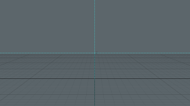
Composition Guides
To assist you in organizing elements within a scene, Modo provides a number of camera overlay guides based on common compositional techniques. The guides are divided into two main types:
• Grid - Symmetrical grid-lines spaced at regular intervals, and a grid based on the golden ratio.
• Golden Rectangle - Division of space based on the golden ratio. This can be drawn as square and rectangular sections, a logarithmic spiral, or both.
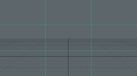
Most of the Grid types consist of equally spaced lines. For example, the Rule of Thirds splits the view into three equal rows and columns. This is a popular compositional guideline in painting and photography, which recommends that important compositional elements (such as the horizon) should be placed along the lines, or at intersections.
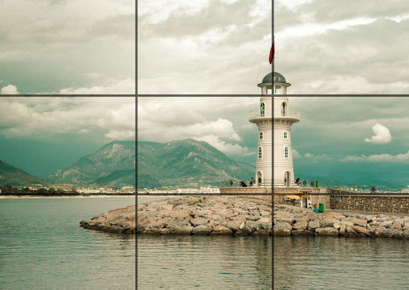
The image above illustrates the rule of thirds in practice. A thirds grid has been overlaid to demonstrate the compositional technique. Notice how the coastline and the lighthouse are closely aligned to the grid lines.
The Golden Ratio Overlays
Grid lines that are spaced equally provide a simple and popular means of composition. However, some argue that the ratio of proportions provided by the golden ratio provides a more natural and pleasing relationship. The golden ratio has its origins in ancient mathematics and is a ratio of proportions that is believed to create visual harmony. The actual value of the golden ratio is a little over 1.618 and has been assigned the greek letter  (phi) . You can use the guides in Modo to help you apply the ratio with a high degree of accuracy.
Note: If you have two lengths a and b, the ratio of their lengths is a:b. For the lengths to conform to the golden ratio, the ratio of a:b must be equivalent to the ratio a+b:a. In other words, a/b = (a+b)/a.
Modo provides a Golden Ratio grid in the Grid list (also known as a Phi Grid). Each line is intersected so that the lengths at either side of the intersection conform to the golden ratio.
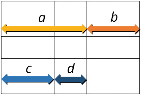
The image above shows a golden ratio grid; the ratio a:b conforms to the golden ratio, as does c:d. This also applies vertically. In practice, you'd simply use the grid lines to position important compositional elements, just as you would with the other grids.
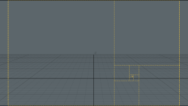
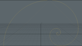
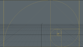
Modo provides an overlay based on repeated division by the golden ratio, in the Golden Rectangle option. A golden rectangle has dimensions that conform to the golden ratio. This gives rise to an interesting property of the rectangle: If you divide the rectangle into a square and a smaller rectangle, the smaller rectangle is also a golden rectangle. By repeated subdivision, the Golden Rectangle grid is formed. By drawing a quarter circle through each square, a spiral is formed. This is known as a Logarithmic Spiral as the radius increases exponentially from the smallest square. The image below shows a sub-divided golden rectangle and the logarithmic spiral.
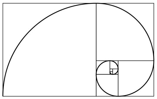
Why would you use this layout in Modo? Again, it presents an alternate set of lines to which you can match compositional elements. When used properly, the spiral can help guide a viewer's eye through a scene and ultimately to the main focus point. The small part of the spiral can be placed over the main focus point, with the rest of the image roughly distributed according to the proportions of the squares.
Composition Guides Properties
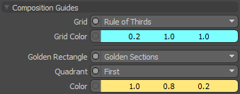
|
Composition Guides |
||||||||||||||||
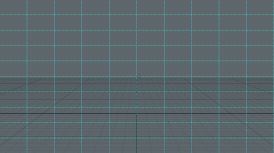
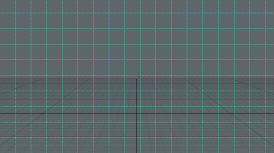
|
Grid |
The type of grid. • Rule of Thirds - A 3x3 grid made of lines spaced equally along the horizontal and vertical. • Center Lines - Bisects the viewport horizontally and vertically. • Golden Ratio - A basic Phi Grid. Each line divides the line it intersects according to the golden ratio. • Tenths - A 10x10 grid made from line spaced equally along the horizontal and vertical. • Square - A grid consisting of squares. The height of each square is equal to one tenth of the viewport height. • Off - Hide the grid. |
|||||||||||||||
|
||||||||||||||||
|
Grid Color |
Use this to set the color of the grid. |
|||||||||||||||
|
Golden Rectangle |
Divide the grid into regions by using the golden ratio. • Golden Sections - A grid formed by repeated division into squares and golden rectangles. • Logarithmic Spiral - A logarithmic spiral whose growth factor is equal to the golden ratio. • Sections and Spiral - Both of the above. • Off - Hide the lines. |
|||||||||||||||
|
||||||||||||||||
|
Quadrant |
Choose the viewport quadrant in which to place the center of the spiral. |
|||||||||||||||
|
Color |
The color of the Golden Rectangle lines. |
|||||||||||||||
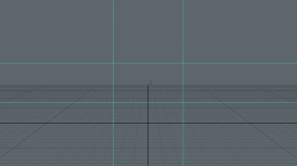
Lines
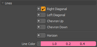
In addition to grids, Modo offers a set of diagonal lines and a horizon indicator to assist with composition. The lines help you place objects along the diagonal using common reference points, such as the corners, or center of the image. The horizon is a useful reference to show camera orientation with respect to the world. You can combine different types of lines as required.
|
Lines |
|
|
Right Diagonal |
Draws a diagonal line from the top-left to the bottom-right of the viewport, with two perpendicular lines that connect to the other corners.
|
|
Left Diagonal |
The reverse of the right diagonal.
|
|
Chevron Up |
Draws a chevron with its apex at the top of the viewport.
|
|
Chevron Down |
Draws a chevron with its apex at the bottom of the viewport.
|
|
Horizon |
This indicates the horizon in relation to the current camera roll position. The horizon is always drawn at the center of the viewport and is updated when the camera is moved.
|
|
Line Color |
Allows you to choose the color of the lines. |
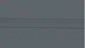
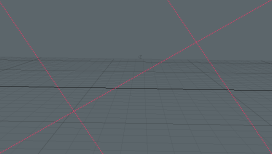
Stereo Camera Volume
The separation of matching pixels in left and right stereo images is referred to as parallax. On the camera's convergence plane, which corresponds to the TV/Movie screen as far as the audience is concerned, there is no parallax. Objects at that distance appear to be in the same plane as the screen. Objects further than the convergence plane appear to be pushed back into the screen. The farther back they are, the greater the separation (parallax) between those pixels. Things in front of the convergence plane appear to be in front of the screen, and also have increasing parallax, though the images are shifted in the opposite direction.
If a scene exceeds a certain parallax amount, viewers may experience discomfort, or the intended effect could be ruined entirely. Conversely, if the scene doesn't have enough volume, then the stereo effect is barely noticeable. The amount of parallax into and out of the screen is critical to monitor when setting up a shot. Directors are even starting to plot depth scores so they can keep the parallax in a safe range, using it as a storytelling element as well as to catch sharp jumps which can be disturbing to viewers.
The Stereo Volume package on the camera enables you to define stereo volume by setting the front and back parallax amounts. You can then either use it to make sure the objects stay in range, or to measure shots by setting keyframes so it always matches the nearest and farthest elements in the scene. To get the Depth Score, just screen capture the Graph Editor.
|
Option |
Description |
|---|---|
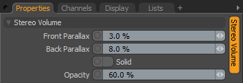
|
Stereo Volume |
|
|
This refers to the amount of depth of your scene between the front-most and back-most elements. It is an important quantity for designing a stereo image. It is referred to as a volume because it includes the entire space width, height, and depth of the frame. It is also related to the stereo budget, which is yet another way of saying the amount of depth used by the scene. You can activate the display of this important visual guide in the 3D viewport by enabling the Show Stereo Volume option in the Display tab. Once enabled, the following options appear in the Properties panel when the Camera Item is selected. |
|
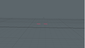
|
Front/Back Parallax |
This parameter sets the desired front and back parallax amounts. It is given as the separation distance's percentage of the screen width. When you set this, Modo computes the distance from the convergence plane where objects have that parallax amount, and draws the front or rear plane there. There are also two circles drawn with centers that are separated by the parallax amount. |
|
Solid |
When enabled, draws volume as filled quads, instead of outlines, making its apparent area more obvious. |
|
Opacity |
Determines the opacity of the drawn volume guides. |