Fusion Surface Strips
Strips are a primary geometric element of a Fusion model. They are the surfaces around the intersecting edges of the source mesh. You can edit strip properties to determine the smoothness, size, or flatness of the strip. Surface Strips are also used for embossing and extruding meshes. Surface strips are useful for smoothing or beveling edges, as well as to create clean topology for when the Fusion Item is converted to a polygonal mesh.
Surface Strip Types
A number of surface strip types are found in the Fusion tab under Set Mesh Role.
|
|
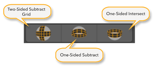
Creates a two-sided surface strip on the primary Fusion Item. A 90 degree grid is created between the corners of the intersection. The Fusion Item remains unchanged. Moving the mesh item moves the strip on the Fusion Item's surface. Tip: You can apply this to one or more primary Fusion Items with the mesh item used to create the surface strip. Selecting one or more primary items and clicking UnTrim removes the surface strip. Clicking Trim reapplies the surface strip. |
|
|
Subtracts the mesh item from the Fusion Item at the trim line and creates a single-sided surface strip. It performs the trim and leaves one half of the surface strip on the trimmed primary Fusion Item. No new surfaces are added by the trimming mesh item. |
|
|
Intersects the mesh item with the Fusion Item and creates single-sided surface strips along the cut edges. This function performs the trim and leaves one half of the surface strip on the trimmed primary Fusion Item. No new surfaces are added by the trimming mesh item. |


Holding the Alt key and clicking these controls allows you to change the mesh's role, but maintain its relationship to Primaries.
Surface strips are created at the junction of two combined objects, and so it is also possible to use meshes as a source for surface strips.
Creating Surface Strips
Surface strips are created automatically along the seam between meshes when a trim or mesh role is assigned. The example below shows you how to use meshes to create surface strips on a Fusion Item as well as how to edit them.
Note: The first time you create surface strips, we recommend using the Fusion Item properties used in the example. For a full list of Fusion Item properties, see Fusion Item Properties.
Note: Edits to strips will not update unless Override Defaults is enabled. This can be found in the Fusion Strip tab in the Properties window.
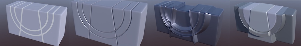
- Use the Fusion Ready Presets window to load three Qbic meshes into your scene.
- Position the meshes so that they all overlap, as shown in the image below. The overlapping meshes create the fusion strips once fusion roles have been set.
- Select the mesh to which you want to apply the strips from the Items list. In this example, the mesh we want to select is the cube at the back.
- Navigate to the Fusion tab, and click the New Fusion button to convert the mesh to a Fusion Item.
- Select the meshes overlapping the Fusion Item from the Items list. The overlapping meshes are used to create the surface strips.
- Click
 to create a Two Sided Subtract Grid. This button can be found under the Set Mesh Roles submenu in the Fusion tab.
Note: Primitive meshes can also be used to create Fusion Strips, but for the cleanest results use Qbic meshes as they are fully optimized for the assembly of fusion meshes.
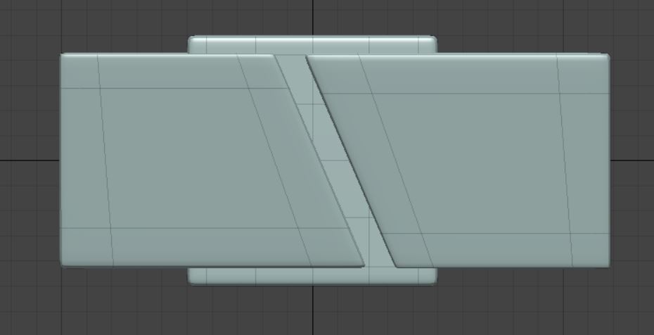
These steps produce a Fusion Item with two surface strips, but there's no limit to the number strips you can create.. By default, these strips will be quite thin but the next section of this page will teach you how to change the Width and Profile of these strips.
Curves, Beziers or B-Splines can also be used to create surface strips on Fusion Models.
Editing Surface Strips
Often, you might find yourself wanting to change the width, profile or density of your strip in order to create cleaner topology for your model once it's converted into a mesh item. Fusion strips can be easily edited in the Fusion Strip tab in the Properties menu. This section with go over what strip parameters can be edited and how to do it.
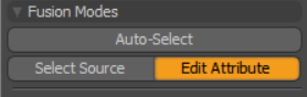
Before you can edit strips, you need to be able to select them. To edit the attributes of a Fusion Item, make sure that Edit Attributes is selected. Edit Attributes can be found under the Fusion Modes menu in the Fusion tab.
With Edit Attribute enabled, there are two ways to select Surface Strips:
• Double-click any strip on your mesh to select all strips in a fusion.
OR
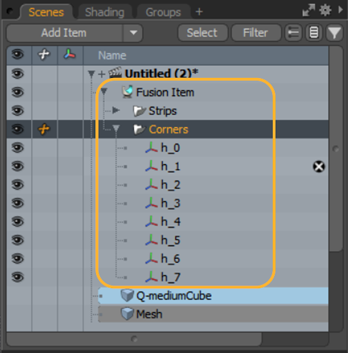
• Select your Fusion Item in the Items List and expand it to select individual strips.
Once expanded, you will see two folders: Strips and Corners. Within the Strips folder, you can view all the strips that are a part of your mesh. From there you can individually select strips.
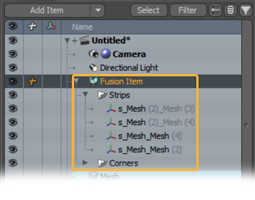
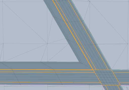
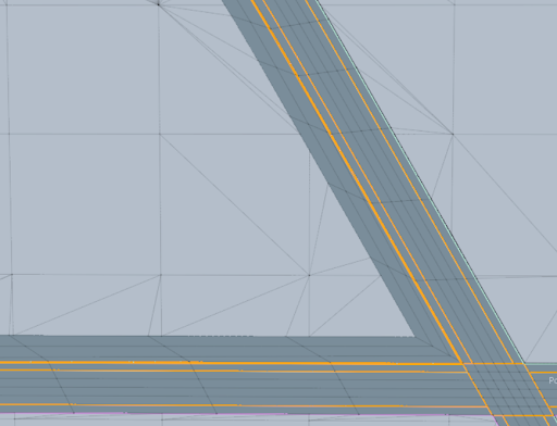
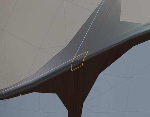
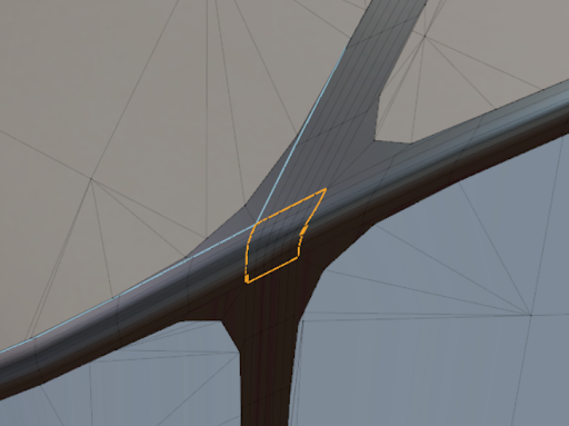
Selected strips are highlighted in orange.
Note: For more information on corners, see Corner Strips and Skirts.
Selected strips can be edited in the Fusion Strip tab, which can be found in the Properties menu. Within the Fusion Strip tab, you are able to change the width, angle and density of your strip.
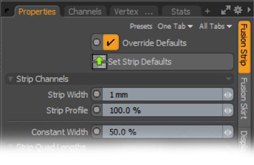
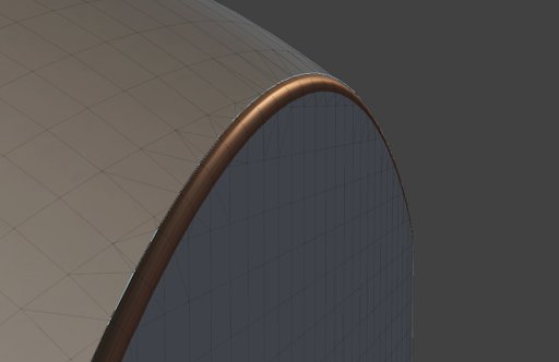
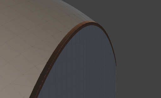
Strip Width controls the width of the strip you have selected.
|
|
|
|
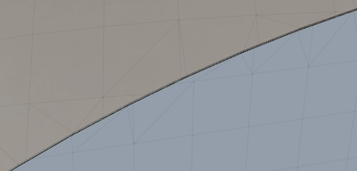
Strip set to default width. |
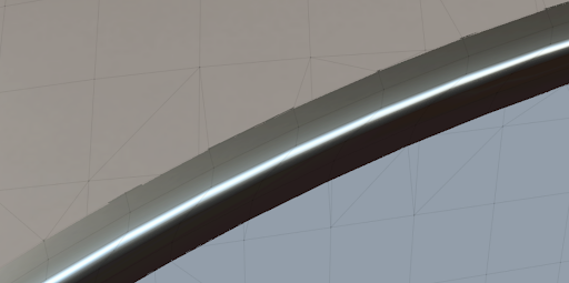
Strip set to 30mm. |
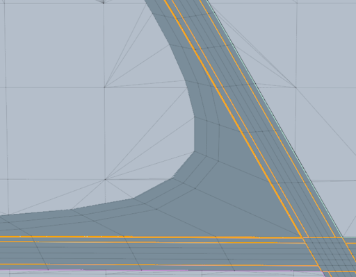
The Strip Profile parameter controls the roundness a strip. The lower the number, the flatter the curve and the higher the number the rounder the curve.
|
|
|
|
|
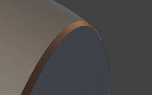
Profile set to Zero. |
Profile set to 100. |
Profile set to 200. |
|
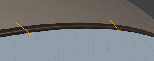
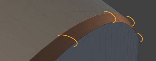
Tip: If you click and drag in the parameter boxes for Strip Width and Strip Profile, yellow guides will appear and give a real-time estimate of how flat/cured/wide your strip will become. |
|
|
|
|
|
Guides for Strip Width. |
Guides for Profile. |
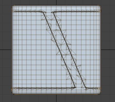
The Strip Quad Lengths parameters allow you to adjust the amount of quads present in the strips, as well as how close together they are. The lower the Base Length and Adaptive Length, the denser your strip will be. Higher Base Length and Adaptive Length values produce sparser strips.
|
|
|
Strip Quad Lengths parameter menu |
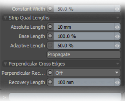
Absolute Length makes sure that the distance between each quad is the same throughout the whole strip.
|
|
|
|
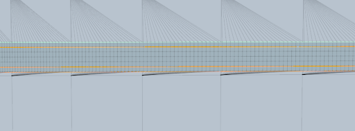
Base and Adaptive Lengths set to 5%. |
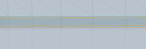
Base and Adaptive Lengths set to 100%. |
Note: Edits to strips will not update unless Override Defaults is enabled. This can be found in the Fusion Strip tab in the Properties window.
Corner Strips and Skirts
Corner Strips are a type of surface strip created where two Surface Strips join or intersect. Corners are useful when editing the width of strips in specific areas of a mesh or increasing the density of a mesh at an intersection to allow for better topology on post-Fusion models.
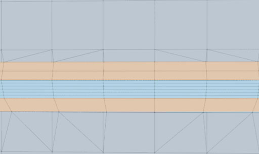
Skirts are an additional piece of geometry that you can add to a Surface Strip to add extra width and ensure better topology for Post-MeshFusion modeling.
|
|
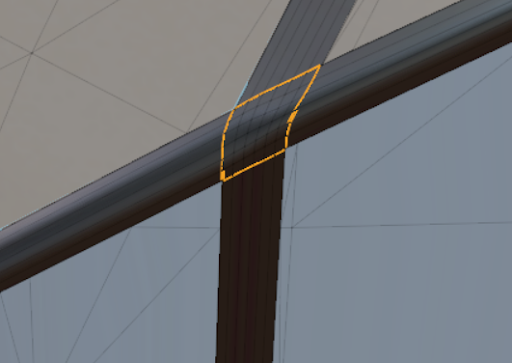
|
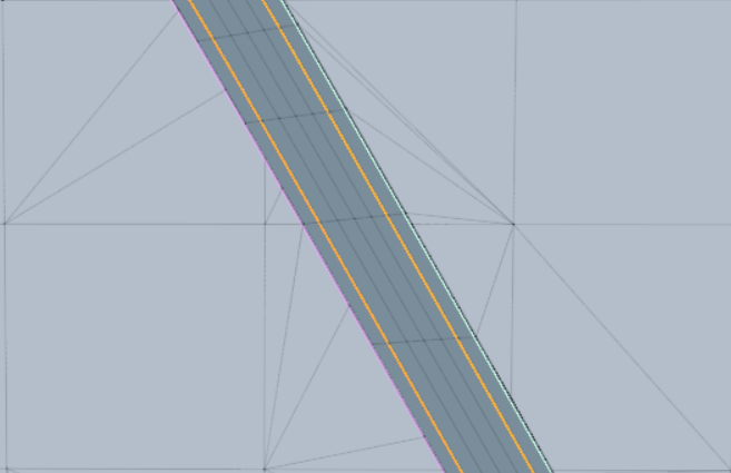
Surface Strip with a Skirt added to it. The skirt is highlighted in orange. |
Adding Skirts
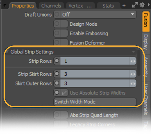
To add skirts to your strip, select your Fusion Item in the Items List so that the Fusion tab becomes available in the Properties window in the lower-left corner of your Modo window.
Within the Fusion tab in the Properties window, scroll down to the Global Strips Menu sub-menu. Here you can input how many Skirt Rows you want applied to your strip.
Editing skirts
After you have your skirts set up, there are two ways you can edit them:
• If your Fusion item has any intersecting strips, select the corner of the strip to which you want to add a skirt.
OR
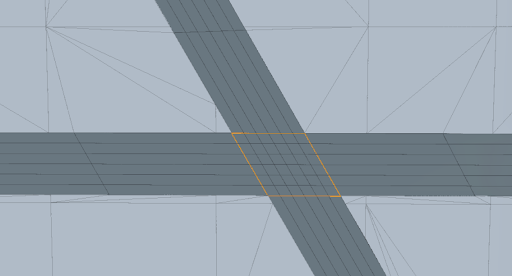
• Select the patch (an area of Geometry surrounded by strips) that you want to add a skirt to. Patches can be selected by double-clicking the patch. Once selected, they are highlighted in orange.
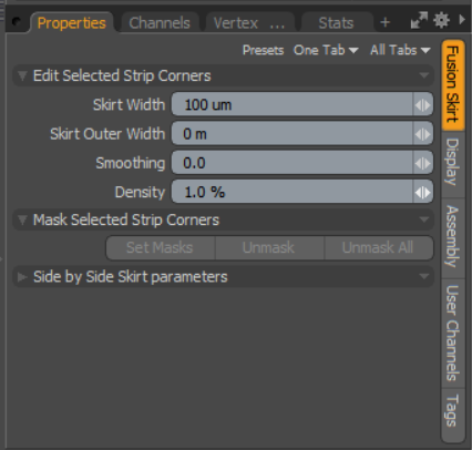
Once you have selected your patch or corner, navigate to the Fusion Skirt tab in the Properties window. In the Fusion Skirt tab you will be able to edit the Width and Outer Width of the skirts, as well as the skirt’s Smoothing and Density.
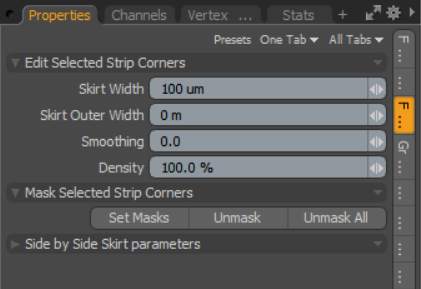
Skirt Width allows you to edit the thickness of the skirt you have selected.
Within the skirt, two rows of Geometry will be produced. These help maintain edge integrity when the Fusion Item is converted to polygonal mesh and subdivided. Skirt Outer Width then allows you to set how far away from the outer edge of your skirt you want inner rows to be.
|
|
|
|
Skirt with Outer Width set to 15mm. |
Skirt with Outer Width set to 5mm. |
Smoothing allows you to reduce the sharpness of any corners or joints within your skirts.
|
|
|
|
Smoothing set to 0. |
Smoothing set to 10. |
Density controls how much or how little polygon density you have in your skirt and strip. As with Adaptive and Base Length in the Fusion Strips tab, the higher the number, the fewer polygons there are and the lower the number, the more there are.
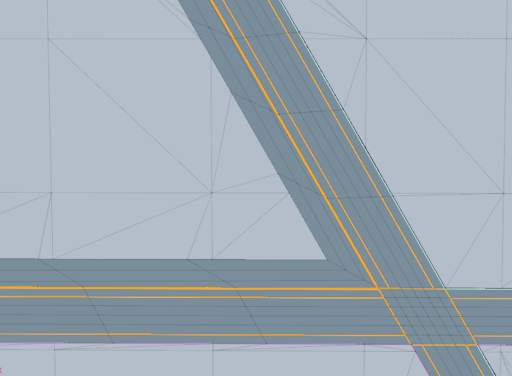
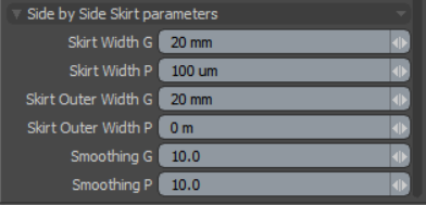
When selected, each strip has a green side and a purple side. Within the Side by Side Skirt Parameters menu each side is indicated by P for Purple, or G for Green. For more in depth editing of skirts, you can also use the Side by Side Skirt Parameters menu.
Use the Side by Side Skirt Parameters, to change the Width, Outer Width and Smoothing of each side. These parameters are the same as the ones covered earlier on in this topic, but instead of affecting the whole skirt only the side you are editing will change.
Editing Corner Strips
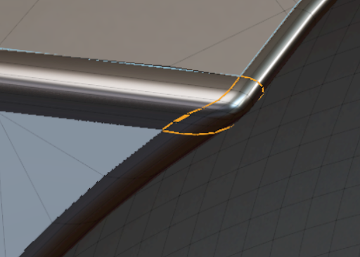
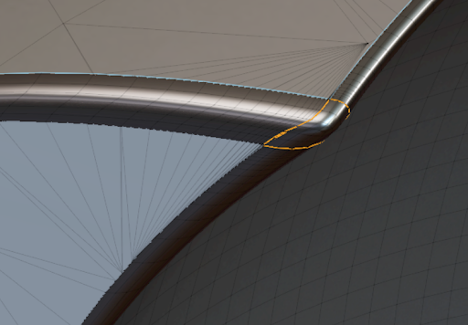
Corner strips are selected in the same way as surface strips are, but to select individual corners, navigate through the Corners folder instead of the Strips folder. Selected corner strips are outlined in orange.
Once you have a corner selected, the Fusion Skirt menu will is displayed in the Properties window.
Skirt Width will increase the widths of any Surface Strips that are connected to the corner, while smoothing will soften or sharpen the edges where two or more strips intersect.
However, corner smoothing must be used in conjunction with skirts and Skirt Rows must be added for it to work.
|
|
|
|
|
No Smoothing. |
Smoothing with no Density. |
Smoothing with Density. |
Density changes how many polygons surround the outside of the corner. This tool is helpful for creating cleaner topology in a post-fusion model and is also useful for creating tighter corners when increasing Smoothness.
|
|
|
|
Density set to 100%. |
Density set to 1%. |
Converting Edge Weights to Strips
In addition to surface strips, Modo can convert edges with 100% weight values to strips automatically. You can use the edge weights on sharp creases to achieve the same strip width and profile as the strips at intersections between different source meshes. There are a number of restrictions on edges you can convert to strips:
-
The selected edges must continue all the way to the end of the mesh, they cannot be open-ended.
-
The edge weighting must be set to 100%, any other value is not converted to strips.
-
The edges can not cross each other and the edges must have a noticeable crease, either a ridge or a gully.
-
The edge ends must be “capped” by another fusion source item.
-
Select the edge or edges you want to convert to strips in the viewport.
-
Assign the edges a weight value of 100%.
You can quickly assign a weight value by pressing Shift+W and entering 100% in the Vertex Map Weight viewport Weight control. -
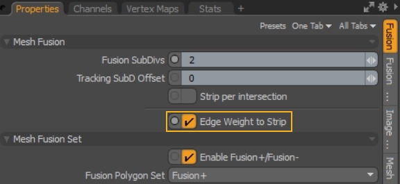
Enable Edge Weight to Strip in the source item Fusion tab.
-
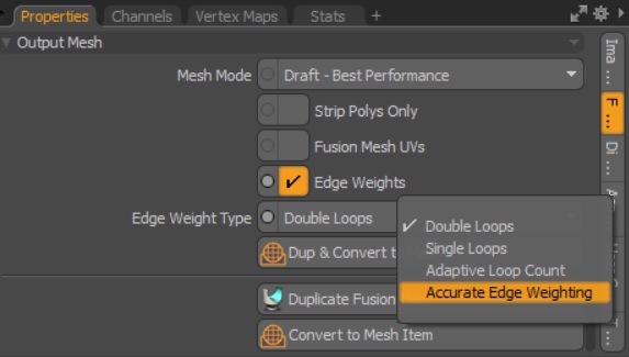
In the Output Mesh properties, enable Edge Weights and set the Edge Weight Type to Accurate Edge Weighting.
The weighted edges are converted to strips and you can control them as you would any other Fusion strip.
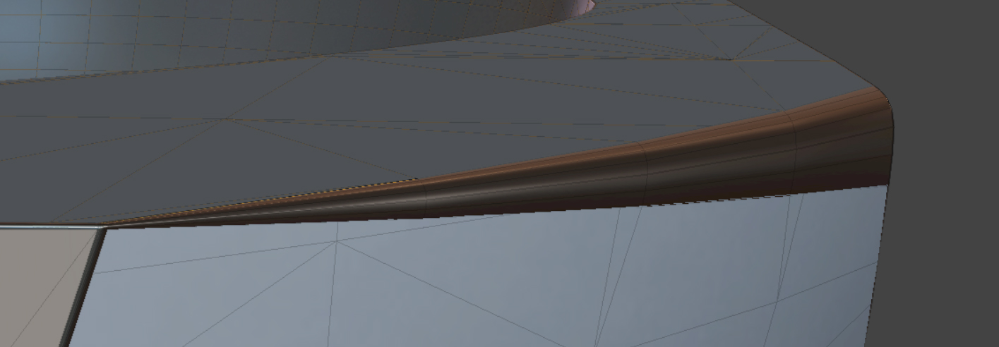
Adjusting the Start and End Width of Strips with Variable Strip Widths
You can also adjust the start and end width of your Fusion Strips. This allows you to get final control over how sharp or beveled your edges are, with a smaller start or end value causing a sharper edge and a larger start or end width creating a rounded, or beveled, edge.
To use Variable Strip Widths:
- Select the Strip you want to change the Variable Width of
- In the Fusion Strip tab in the Properties panel, check the Tweak Variable Strip Widths option
- Adjust the Start Strip Width and Strip End Width parameters as needed
Once enabled, Start Strip Width and Strip End Width parameters become available
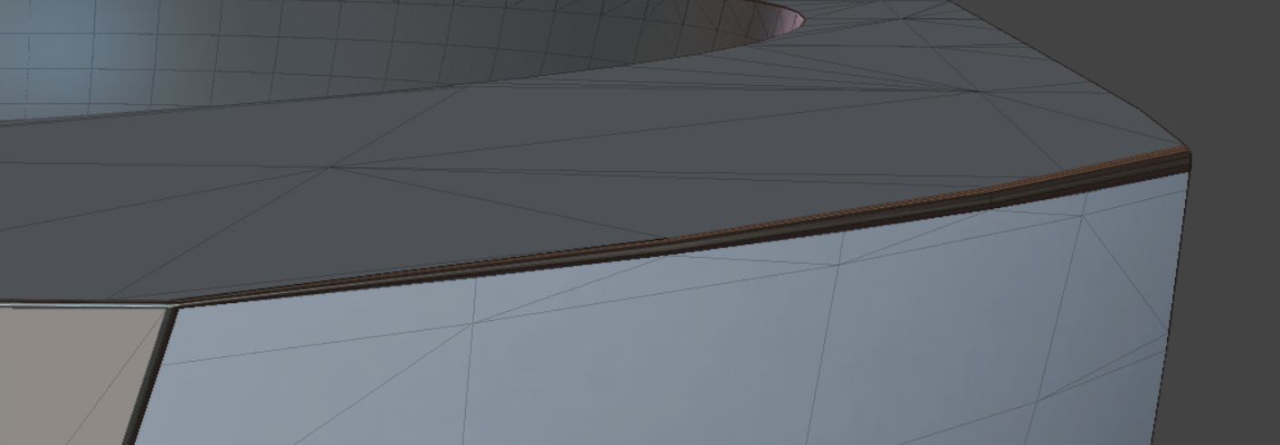
When adjusting these parameters, keep in mind that the smaller the width of the strip is, the sharper you edge will be while the wider the strip is, the more rounded it will be. This allows you to create a gradated edge on models.
|
|
|
|
Strip with Start Strip Width set to 16 mm while End Strip Width is set to 1 mm |
Strip with Start Strip Width set to 5 mm while End Strip Width is set to 1 mm |